GE MEDICAL SYSTEMS PROPRIETARY TO GE
D
IRECTION 2294854-100, REVISION 3 LOGIQ™ 9 PROPRIETARY MANUAL
Chapter 8 Replacement Procedures 8-125
.
6.) Replace AC Controller as described in AC Controller Replacement Procedure on page 8-106.
7.) Turn the AC Controller as necessary to facilitate connecting the cables.
8.) Secure the AC Controller to the chassis.
9.) Replace External I/O as described in Internal I/O Replacement Procedure on page 8-128.
10.)Plug the External I/O into it’s socket on the Internal I/O. Replace the screw that attaches the external
I/O to the Internal I/O rear wall.
11.)Replace the two screws that attach the External I/O to the chassis leg.
12.)Connect the telephone and interface cables to the rear of teh External I/O Assembly
13.)Replace the Modem and it’s power supply.
14.)Reconnect the power cable from the Front End Card Rack along with the Fan Speed Control cable
15.)Install Air Duct cover. Slide it in over the Fan Assembly then reach in and force the front down over
the fan.
16.)Secure the cove with four (4) screws. See Figure 8-135.
17.)Replace Filter Frame and filter media.
18.)Connect Fan cable. See Figure 8-131.
19.)Replace Lower Rear Cover, including different amount of washers and a magnetic lock for Filter
Cover on the upper screws, described in Lower Rear Cover Replacement Procedure on page 8-10.
20.)Replace Rear Handle as described in Rear Handle Installation procedure on page 8-12.
21.)Replace Top Cover as described in Top Cover Replacement Procedure on page 8-8.
22.)Replace Right Side Cover as described in Side Covers (with Bumper) Replacement Procedure on
page 8-5.
23.)Turn Mains Circuit Breaker ON and boot up the system as described in Section 4-3-1 on page 4-2.
Put a hand on the Filter and feel that the Fan draws air into the System.
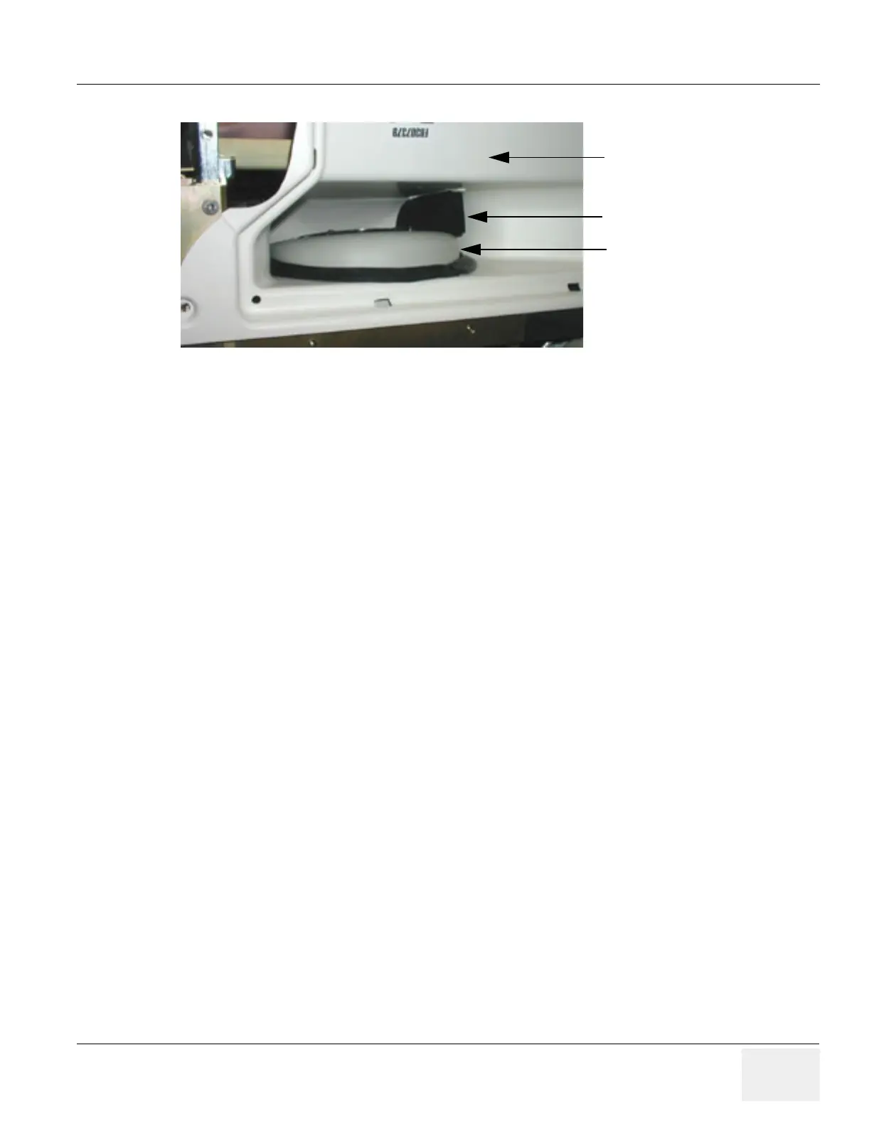
Figure 8-135 Fan Assembly in Position
Cover Air Duct
Vibration bumper
Top of Fan Assembly