GDM-906X Series User Manual
98
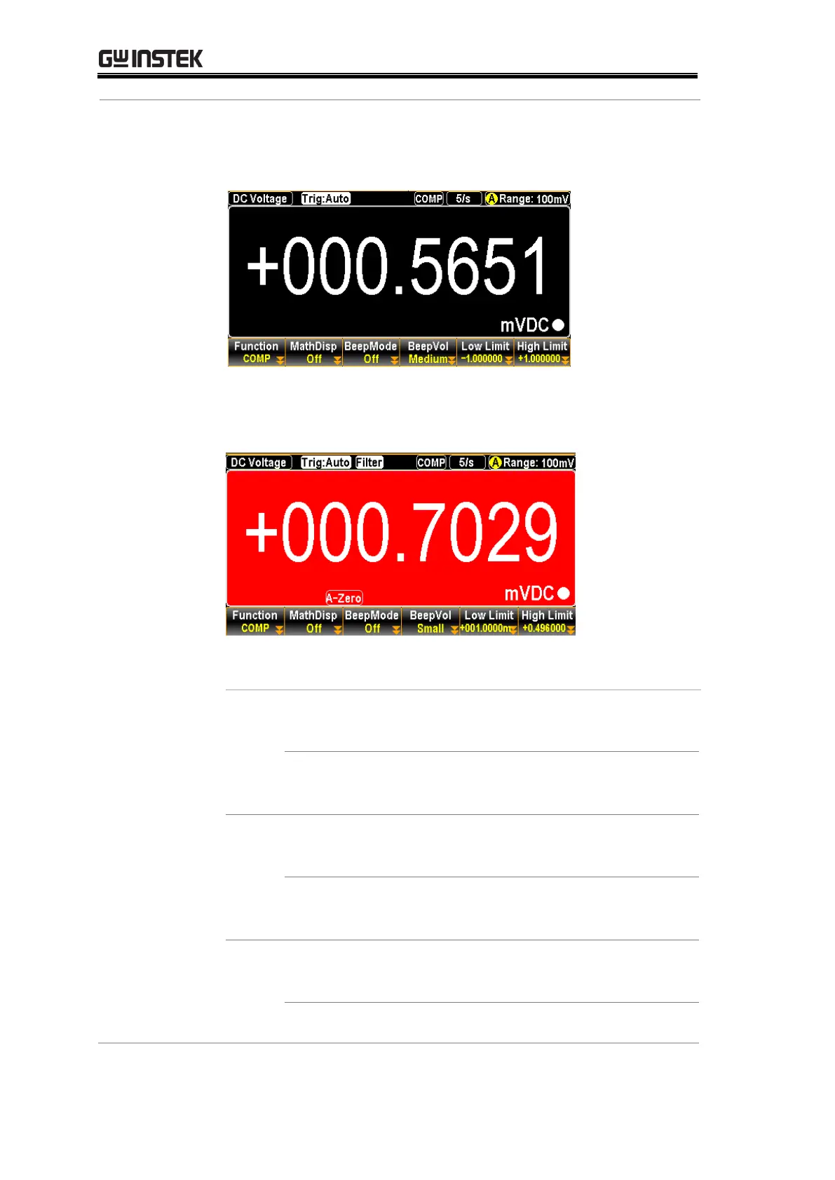
When the measured result is within the range of high and low
limit, the display shows as the figure below with purely black
background indicating the state of “Pass”.
However, when measured result is either above or less than
the limit range, the display appears as the figure below with
boldly red background indicating the state of “Fail”.
See the contents below for more details of each state in
compare mode
If the compare result is High, the relative pins of
digital I/O port in action are as the follows.
Digital I/O: FAIL Out (Pin 6) and HIGH Limit
FAIL Out (Pin 7) are activated.
If the compare result is Low, the relative pins of
digital I/O port in action are as the follows.
Digital I/O: FAIL Out (Pin 6) and LOW Limit FAIL
Out (Pin 8) are activated.
If the compare result is Pass, the relative pin of
digital I/O port in action is as the follows.
Digital I/O: PASS Out (Pin 5) is activated.
 Loading...