Constellation™ November 2003
7-2 SNMP-Based Network Management
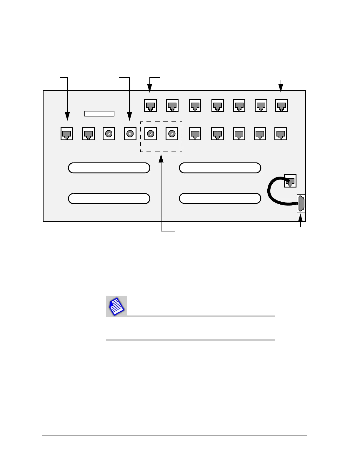
Figure 7-1: Constellation Customer Access Area
In addition to the physical circuits available on the backplane, there is a virtual
Netcom circuit. The Netcom air interface transports and routes IP traffic within
the overhead bits (microwave). Physical interconnection is through the
Ethernet port on the radio. This, along with user configuration, enables the
interface to transport traffic. Configuration examples are given on page 7-6
(standard) and page 7-9 (advanced).
The AUX and ETHERNET ports cannot be used at the
same time.
J16 J36 J17 J18 J31 J23 J24
Wayside Monitor Spur Aux Ethernet Data
Port 1
Data
Port 2
J25
Handset 1
J32
Handset 2
J20
VersaT1lity
J21
VF Port 1
J22
VF Port 2
J15
Can
J19
Keypad
J26
DS3 IN
J27
DS3 OUT
J36
Wayside
In
J35
Wayside
Out
Fan
J29
DS1 17-32 Out
25 1
2650
P14
DS1 1-16 In
125
5026
P15
DS1 17-32 In
125
5026
P15
DS1 1-16 Out
25 1
2650
RJ-45
T1 Wayside
1
BNCRJ-11
E1 Wayside, SDH option only
DE-9
J28
FSCAN