Harris Corporation Constellation™
Detailed Installation Procedures 3-19
INSTALLATION
AND
COMMISSIONING
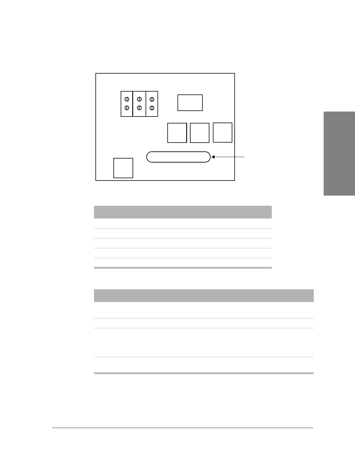
Figure 3-13: Constellation backplane (top left)
Figure 3-14 shows the Alarm I/O pinouts.
Table 3-9: Relay specifications
Characteristic Value
Nominal switching capacity (resistive) 2 A, 60 Vdc
Max. switching power (resistive) 60 W
Max. switching voltage 220 Vdc
Max. switching current 2 A
Min. switching capability 10 µA, 10 mV dc
Table 3-10:Relay outputs
Relay Function Definition
1
2
Local Major
Local Minor
Default relay outputs.
Definable through the Keypad.
3 through 8 Customer-definable output Definable through the Keypad.
Callout Callout relay for orderwire
Indicates that a call is being
received. The customer can use
these outputs for additional call-in
detection.
FA Fuse alarm relay
These outputs can be used for
remote fuse alarm indication.
BAT A
BAT B
RET
24/48VDC
HARRIS Constellation Backplane
TO FUSE PANEL
ALARM I/O
Filter
Filter
Filter Filter
26
1
25
50
External
alarm/control
connector
J1
J2