Harris Corporation Constellation™
Detailed Installation Procedures 3-21
INSTALLATION
AND
COMMISSIONING
a. Verify that the antenna waveguide is grounded according to
recommended or regulatory practice.
b. Determine and prepare the length(s) of flexible waveguide needed to
connect the antenna(s) to the radio.
c. Install the waveguide.
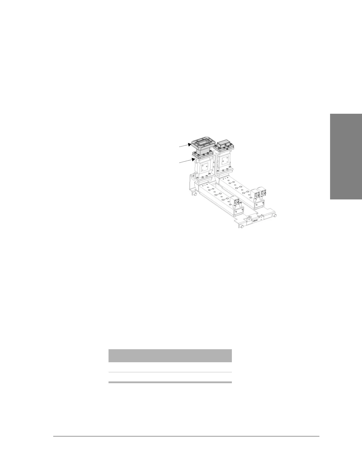
d. Remove the Port Cover from the ACU. See Figure 3-15.
Figure 3-15: ACU
e. Install the optional spacer adapter onto the existing antenna port.
f. Connect the antenna waveguide to the ACU flange.
g. Use the flexible waveguide to interface between the radio’s waveguide
flange and the rigid waveguide. This interface allows flexibility in
movement should a seismic disturbance occur.
h. Secure all cable and waveguide assemblies as required.
i. Pressurize the waveguide, and check all waveguide connections for
leaks. Tighten the joints as required.
4. Test the office battery voltage.
Use a digital multimeter to test the battery (source) voltage. The battery
polarity may be positive or negative with respect to ground.
The following table lists the battery noise requirement.
Source (V) Accepted Value (V)
24 21 to 28
48 42 to 56
Antenna port
Spacer adapter
(optional)