Constellation™ November 2003
D-6 Service Channel
Two Separate Loop Systems
Example A
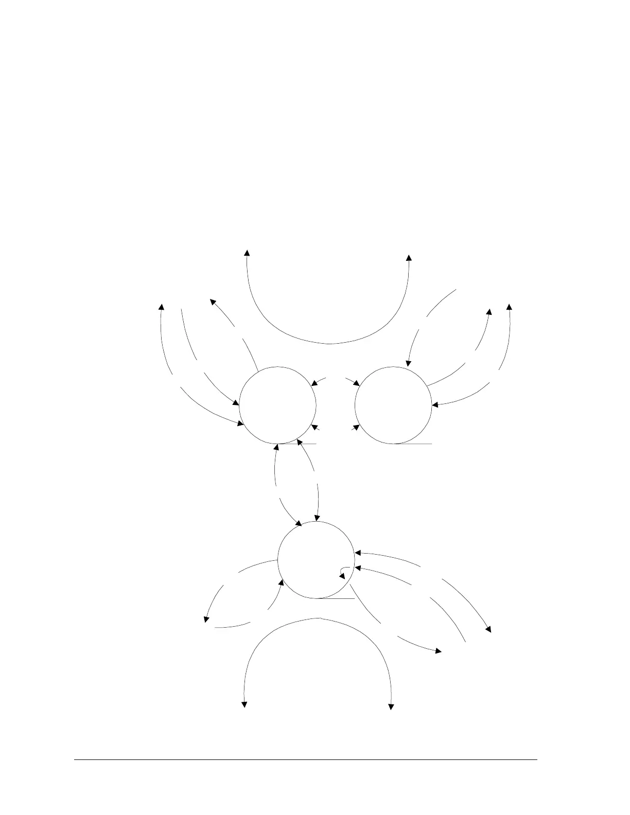
Two Separate Loop Systems, Example A (Figure D-4) shows two loop systems
connected together by two cables. The two loop systems operate independently
and identical as previously discussed. Note that both Slave Terminals in Loop
1 must have the External Pilots enabled.
Figure D-4: Two separate loop systems, Example A
Pilot A
Pilot A
Pilot B
Pilot A
DATA
DATA
Terminal
Slave
Terminal
Slave
Data
VF
External
Pilots
Repeater
Master
VF
Data
Pilot A
Pilot B
DATA
Pilot A
Pilot B
A
A
AB
Loop 1
Loop 2