Constellation™ November 2003
3-20 Installation and Commissioning
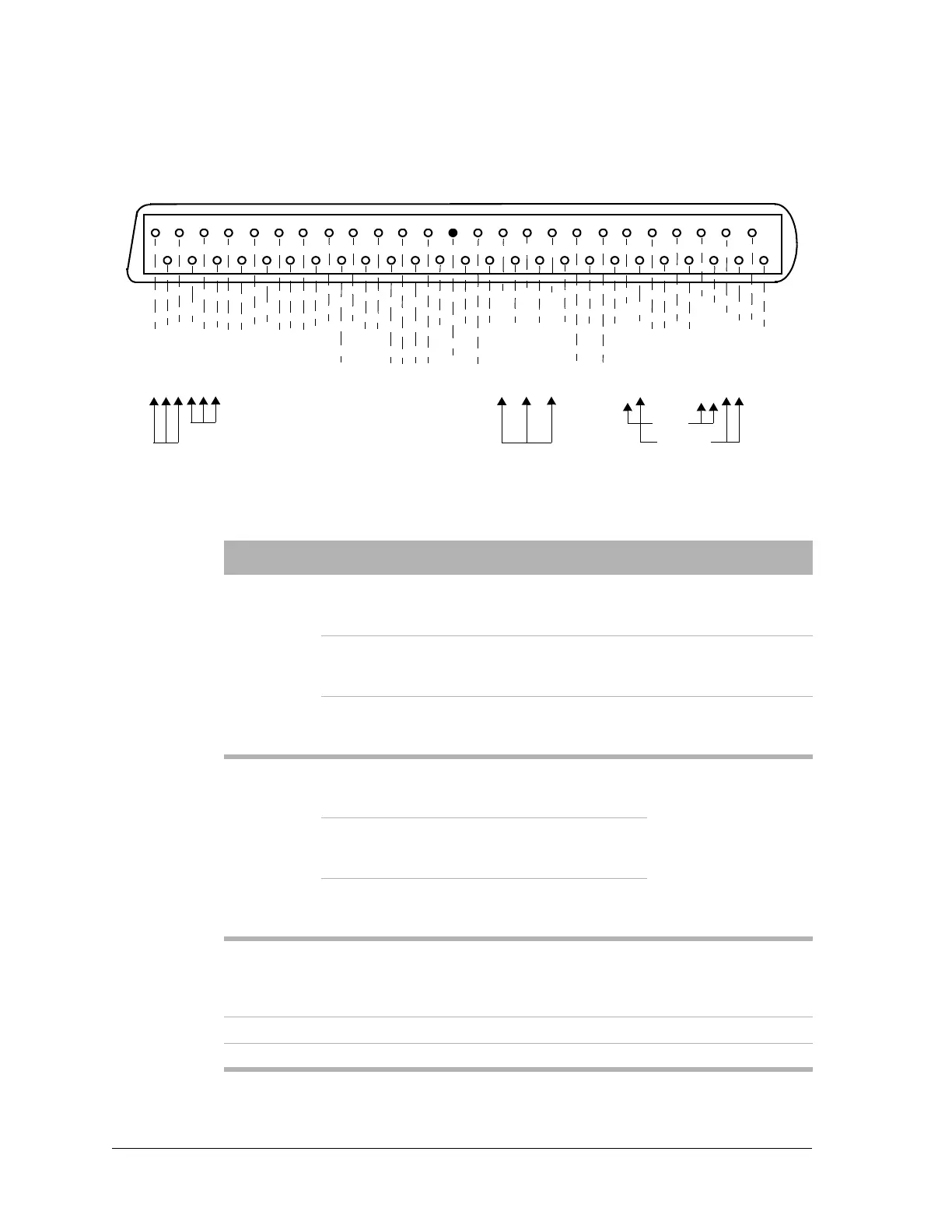
Figure 3-14: Alarm I/O pinouts, J2 (D connector, female)
1
26
27
28
3
29
4
30
5
31
6
32
7
33
8
34
9
35
10
36
11
37
12
38
13
39
14
40
15
17
16
18
41
44
42
43
19
20
45
46
48
47
21
22
23
24
49
50
25
2
Fuse Alarm
Callout
Relay
Fan Alarm
Major
Alarm
(default)
Minor
Alarm
(default)
RELAY 1 NC
RELAY 1 NO
RELAY 1 COM
RELAY 2 COM
RELAY 2 NC
RELAY 2 NO
RELAY 4 NC
RELAY 4 NO
RELAY 4 COM
RELAY 3 COM
RELAY 3 NC
RELAY 3 NO
RELAY 5 NC
RELAY 5 NO
RELAY 5 COM
NC
RELAY 7 COM
RELAY 7 NO
RELAY 7 NC
NC
NC
NC
NC
EXT ALARM 1
GND
EXT ALARM 2
NC
EXT ALARM 3
FAN ALM RELAY NO
EXT ALARM 4
FAN ALM RELAY COM
EXT ALARM 5
FAN ALM RELAY NC
EXT ALARM 6
NC
EXT ALARM 7
NC
EXT ALARM 8
CALLOUT RLY NC
FA RELAY NC
RELAY 6 NC
RELAY 8 NC
RELAY 6 COM
RELAY 6 NO
CALLOUT RLY COM
CALLOUT RLY NO
FA RELAY COM
FA RELAY NO
RELAY 8 COM
RELAY 8 NO
Table 3-11:ACU technical data
Ports
Antenna
port
6 GHz
CMR-137 flange with all tapped
mounting holes for No. 6-32
screws.
CPR-137 spacer
adapter
7/8 GHz
CMR-112 flange with all tapped
mounting holes for No. 6-32
screws.
CPR-112 spacer
adapter
10/11
GHz
UG39/U flange with all tapped
mounting holes for No. 8-32
screws.
CPR-90 spacer
adapter
Expansion
port
6 GHz
CMR-137 flange with all tapped
mounting holes for No. 6-32
screws.
The waveguide
termination can be
removed to gain
access to this port.
Optional waveguide
pieces to interface to
other radios are
available upon
request.
7/8 GHz
CMR-112 flange with all tapped
mounting holes for No. 6-32
screws.
10/11
GHz
UG39/U flange with all tapped
mounting holes for No. 8-32
screws.
Transmit monitor port
SMA female connector. A calibrated monitor port,
approximately
−30 dB down from the top of rack.
The exact number is on the label “Coupling loss from
antenna flange”.
Transmit RF in SMA female connector.
Receive RF out SMA female connector.