Constellation™ November 2003
11-18 Field-Replaceable Units
Removing and Installing the 100 MHz OCXO
1. Place the Receiver Assembly on a flat surface.
2. Disconnect the MCX connector by carefully pulling it up straight from the
printed circuit board. The connector is designated
100MHZ
on the board.
See
Figure 11-13
.
3. Disconnect the power connector from the printed circuit board.
4. Carefully pull out the 100 MHz OCXO from the Receiver Assembly, taking
care not to remove the grommets from the printed circuit board.
5. Remove the SMA cable from the OCXO you have just removed. See
Figure
11-14
.
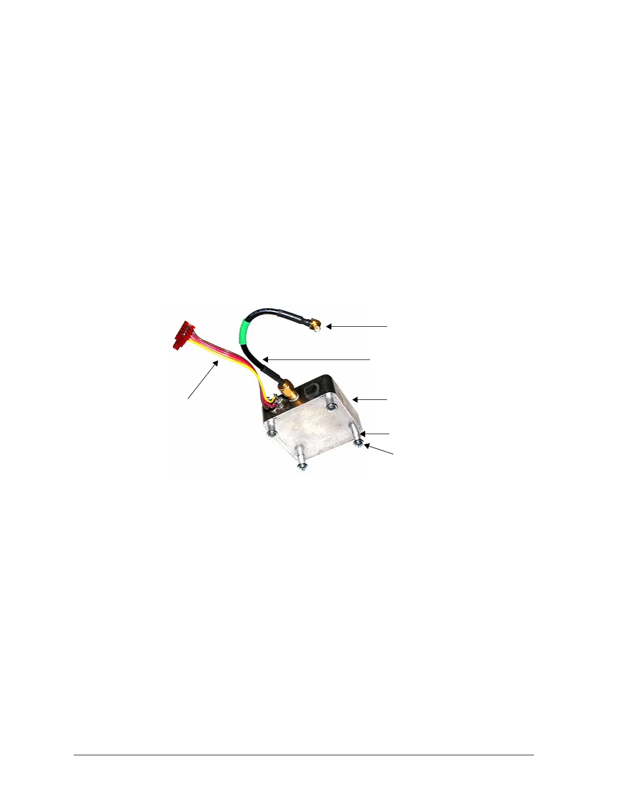
Figure 11-14:100 MHz OCXO
6. Remove and retain the 4 SEMS Phillips screws, washers, and spacers from
the bottom of the OCXO.
7. Obtain a new 100 MHz OCXO.
8. Install the 4 spacers with the SEMS Phillips screws and washers you
removed in step 6 onto the bottom of the new OCXO.
9. Connect the SMA cable you removed in step 5 onto the 100 MHz OCXO.
Do not tighten.
10. Install the new OCXO onto the Receiver Assembly, ensuring the grommets
remain in place.
11. Plug the power connector onto the Receiver printed circuit board.
12. Carefully plug the MCX connector into the receptacle designated
100MHZ
.
13. Use a torque wrench to tighten (8-9 inch-pounds) the SMA connector you
installed in step 9.
14. For Receiver Assembly installation procedures, go to
page 11-20
.
SEMS Phillips screw
and washer (4)
100 MHz OCXO
Power cable
MCX connector
SMA cable
Spacer (4)