Harris Corporation Constellation™
Aligning the Antenna 3-35
INSTALLATION
AND
COMMISSIONING
Aligning the Antenna
1. Align the antenna.
The Keypad reading is not as accurate as using the
RSL/GND test points.
a. Connect a multimeter at the RSL/GND test point of the Receiver
Assembly.
b. Adjust the orientation of each antenna to maximize the voltage
reading.
The voltage reading is negative and approaches zero as the RSL
increases.
For example:
At -50 dBm, the meter reading is -5.0 Vdc.
At -40 dBm, the meter reading is -4.0 Vdc.
See also Figure 3-21.
RSL Test Point
At -21 dBm or higher, a 10 dB attenuator is engaged, resulting in a 1 volt drop
(apparent 10 dB) in the RSL test point reading. The Keypad will display the
corrected (unattenuated) value. At nominally -23 dBm, the attenuator is
disengaged, and the meter will reflect the unattenuated value. See Figure 3-21.
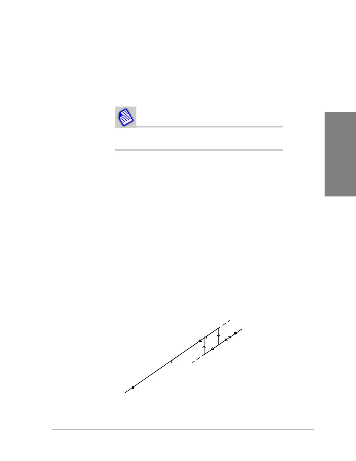
Figure 3-21: RSL measurement
-26 dBm (-2.6 Vdc*)
-70 dBm (-7.0 Vdc)
-20 dBm (-3.0 Vdc)
-29 dBm (-3.9 Vdc***)
(-3.6 Vdc**)
(-2.9 Vdc
#
)
LEGEND
( ) Test point reading.
* Before the attenuator is engaged.
** After the attenuator is engaged.
*** Before the attenuator is disengaged.
#
After the attenuator is disengaged.
-23 dBm
-21 dBm