Constellation™ November 2003
10-6 Troubleshooting Guidelines
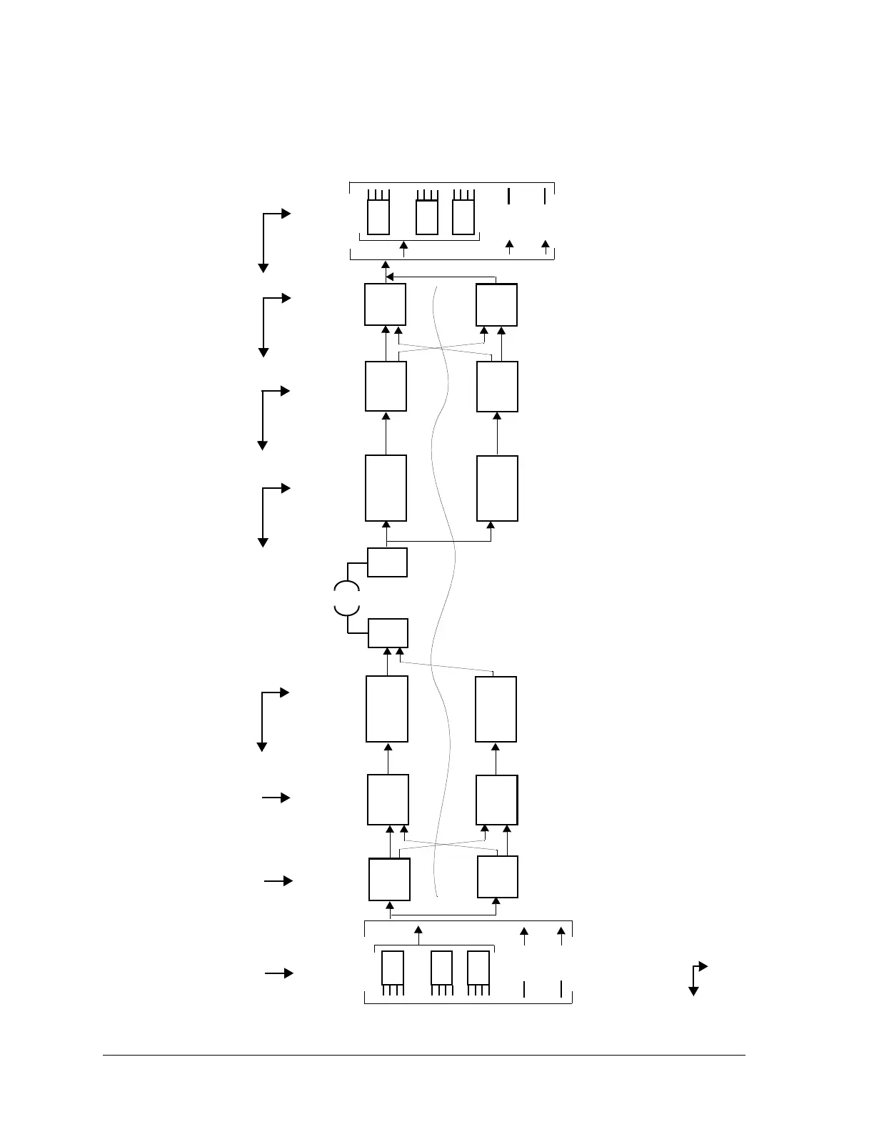
Figure 10-1: Constellation Radio alarm path
Receiver
Assembly
HLM
Modem
ACU
M12 Unit
8
.
.
.
DS3
or
Transmitter
Assembly
Modem
T2 SYNC LO
T1 LOCAL CLK
TRIB OUTPUT FAIL
SYNC LOSS
M12 RX CLK
*
DS3 OUTPUT
FAIL
*
CARRIER LOSS
FEC LOCK
SYNTH LOCK ALM
*
AGC
SYNTH LOCK ALM
*
OUTPUT POWER LOW
NO IF INPUT
TX ENCODER
TX LEVEL
ACU
HLM
1
STBY
M12 Unit
8
.
.
.
DS3
or
1
STBY
Transmitter
Assembly
Modem
HLM
Receiver
Assembly
HLM
Modem
TX TO MODEM ALM
M12 TX CLK
TX TO HLM
ALM
*
This alarm normally signifies a failure in the card.
First, check to see if the fault lies in the card. If not, then check the card to the left
of the diagram.
LEGEND
155
or
155
or