Harris Corporation Constellation™
Loop System Configurations D-7
SERVICE CHANNEL
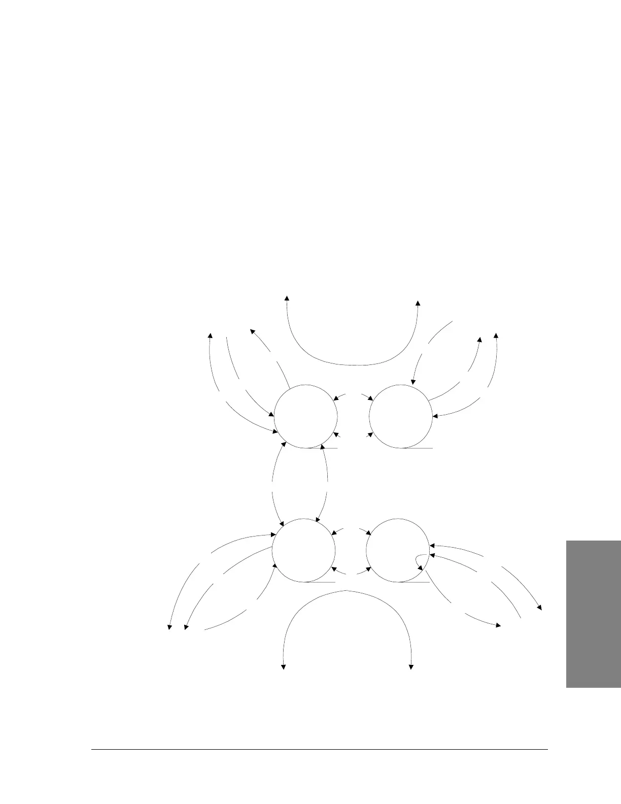
Example B
Two Separate Loop Systems, Example B (Figure D-5) is the same as Example
A. However, the VF and data signals are connected between a Slave Terminal
and a Master Terminal each in its own loop. The system operation is identical
as previously mentioned.
It is important to know not to connect two Slave Terminals with their External
Pilot enabled if each Terminal is from a separate loop. Connecting the pilot
signal from one loop to the pilot signal of the other loop is forbidden.
Note that at no time should a Master site have its External Pilot enabled. This
process is forbidden and will not allow the Service Channel to work properly.
Figure D-5: Two separate loop systems, Example B
Pilot A
Pilot A
Pilot B
Pilot A
DATA
DATA
Terminal
Slave
Terminal
Slave
Data
VF
External
Pilots
Terminal
Slave
VF Data
Pilot A
Pilot B
DATA
Pilot A
Pilot A
Terminal
Master
Data
VF
DATA
A
A
Loop 1
A
A
Loop 2