Constellation™ November 2003
11-10 Field-Replaceable Units
Preparing to Replace the Transmitter Assembly
1. Obtain a spare Transmitter Assembly.
2. Ensure that the correct option of the Multiplier-Filter is installed onto the
Transmitter Assembly.
See Appendix C
for a table of options.
3. For procedure to replace a Multiplier-Filter, go to
page 11-10
.
4. For procedure to replace a Transmitter Assembly, go to
page 11-12
.
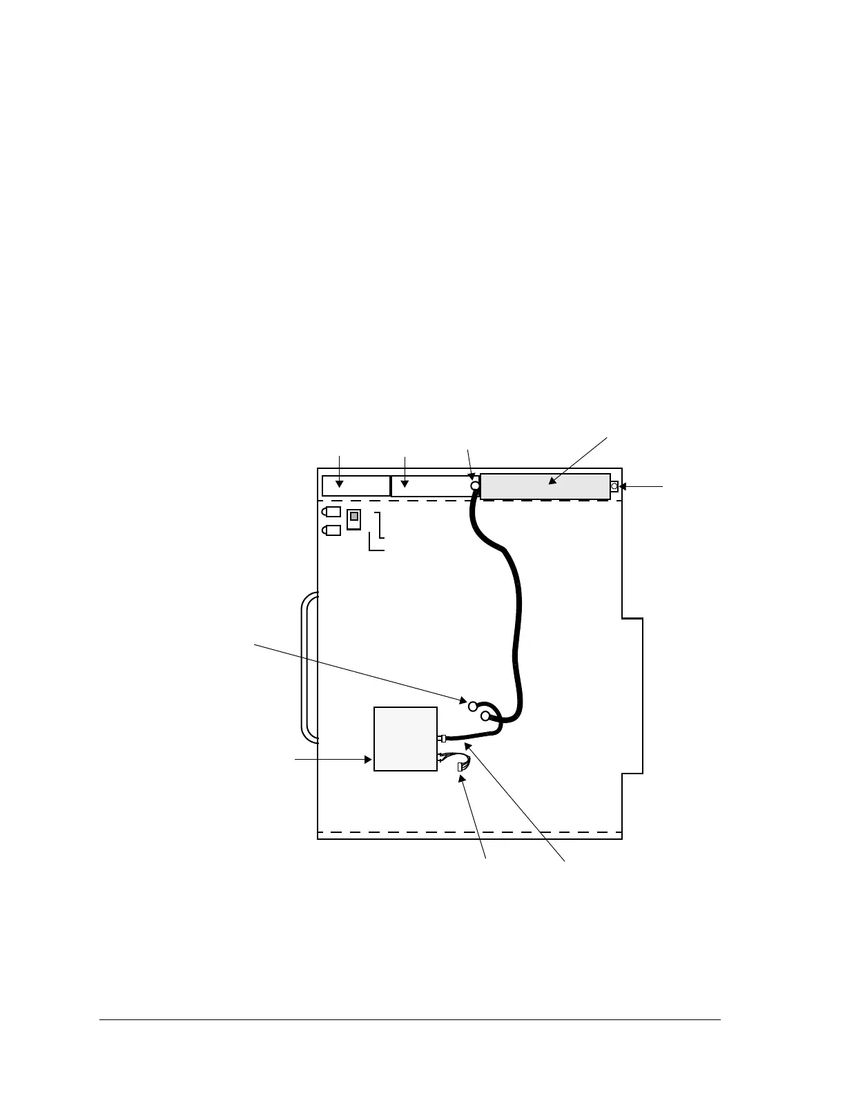
Removing and Installing the Multiplier-Filter
1. Unplug the MCX connector. See Figure 11-10.
Figure 11-10:Transmitter Assembly, component side
2. Unfasten the screw on the right-hand side of the Multiplier-Filter.
3. Unplug the Multiplier-Filter from the Driver Amplifier by pulling the
Multiplier-Filter to the right.
Multiplier-filter
(field-replaceable)
Screw
Driver
subassembly
MCX connector
A
B
SOFTWARE FAULT
HARDWARE FAULT
JP1
Power
amplifier
Note: JP1
settings are for
factory use only.
Do not touch.
100 MHz
OCXO-
amplifier
SMA cable
Power connector
MCX connector
100MHZ