Harris Corporation Constellation™
Loop System Configurations D-3
SERVICE CHANNEL
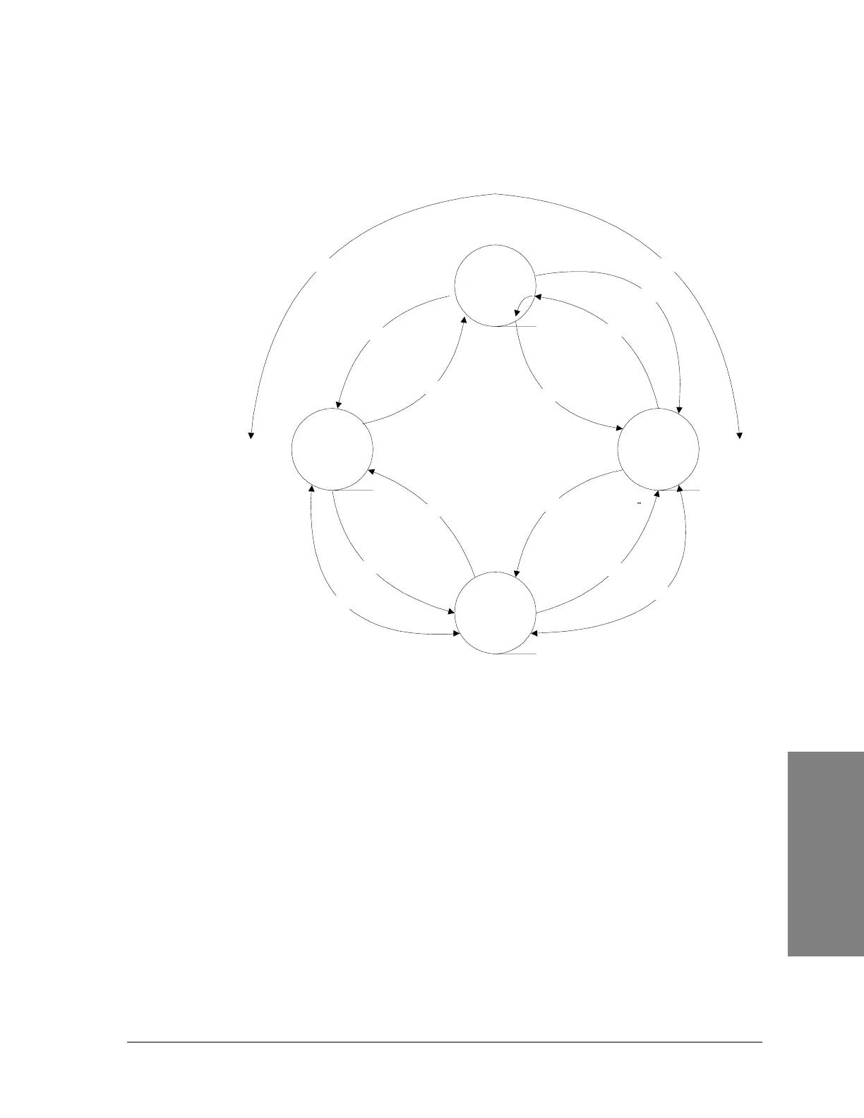
Figure D-1: Single loop system using repeaters
Single Loop System with Two Terminals at
Repeater Site
Single Loop System with Two Terminals at Repeater Site (Figure D-2) shows a
loop system but with two of the system sites having Service Channel Terminals.
The same principle of operation applies here as discussed previously. However,
the setup is different. An external cable is needed to link the VF and pilot
signals between the two Slave Terminals which must enable their External
Pilot.
Repeater
Master
Repeater
Slave
Repeater
Slave
Repeater
Slave
Pilot A
Pilot A
Pilot A
Pilot A
Pilot B
Pilot B
Pilot B
Pilot B
DATA
DATA
DATA
Direction A Direction B
A
A
A
A
B
B
B
B