Harris Corporation Constellation™
Customer Access Areas A-5
WIRING
SPECIFICATIONS
Customer Access Areas
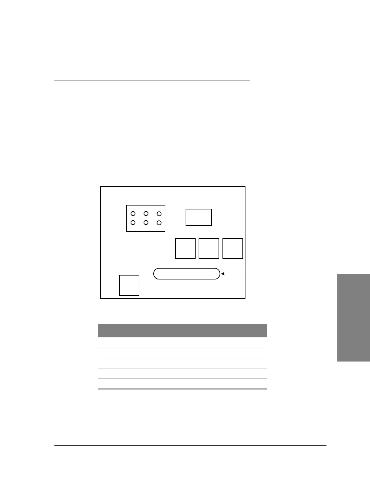
External Alarm/Control Connector
Located at the top left side of the radio, this 50-pin D connector (Figure A-8) is
available for customer-configured alarms. The SPU Controller provides 8 opto-
isolated alarm inputs. The system provides 8 dry-contact, relay outputs as
defined in Table A-2. The Service Channel provides the Callout outputs. Table
A-1 lists the relay specifications.
Figure A-7: Constellation backplane (top left)
Table A-1: Relay specifications
Characteristic Value
Nominal switching capacity (resistive) 2 A, 60 Vdc
Max. switching power (resistive) 60 W
Max. switching voltage 220 Vdc
Max. switching current 2 A
Min. switching capability 10
µA, 10 mV dc
BAT A
BAT B
RET
24/48VDC
HARRIS Constellation Backplane
TO FUSE PANEL
ALARM I/O
Filter
Filter
Filter
Filter
26
1
25
50
External
alarm/control
connector
J1
J2