Constellation™ November 2003
3-16 Installation and Commissioning
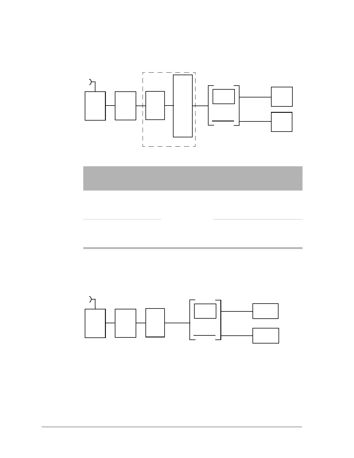
Figure 3-6: Interconnection cabling, DS1 configuration
Note: Avaya Communication, 608C cables, or equivalent.
DS3 Configuration
Figure 3-7: Interconnection cabling, DS3 configuration
Table 3-8: Interconnection cabling requirements
Application
Cable
Length
(feet)
Line
Attenuation/
Equalization
Specifications
1
Digital
channel
bank
0 to
1310
Programmed
through software
22 AWG, 16-pair, tinned
copper, twisted pair, solid,
shielded, PVC, equipped with
drain wire, 100 ohms
2
DS1 cross-
connect
0 to 655
22 AWG, 16-pair, tinned
copper, twisted pair, solid,
shielded, PVC, equipped with
drain wire, 100 ohms
Radio
Modem
HLM
M12
Units
DS1
or
DS1
Jackfield
DS1
Cross-
Connect
Digital
Channel
Bank
Application 1
Application 2
Mux
Radio
Modem
HLM
DS3
or
DS3
Jackfield
DS3 Radio
Repeater
DS3
Multiplexer
Application 1
Application 2
or
or
Avaya 734 cables, or equivalent.