Harris Corporation Constellation™
Detailed Installation Procedures 3-23
INSTALLATION
AND
COMMISSIONING
Terminal
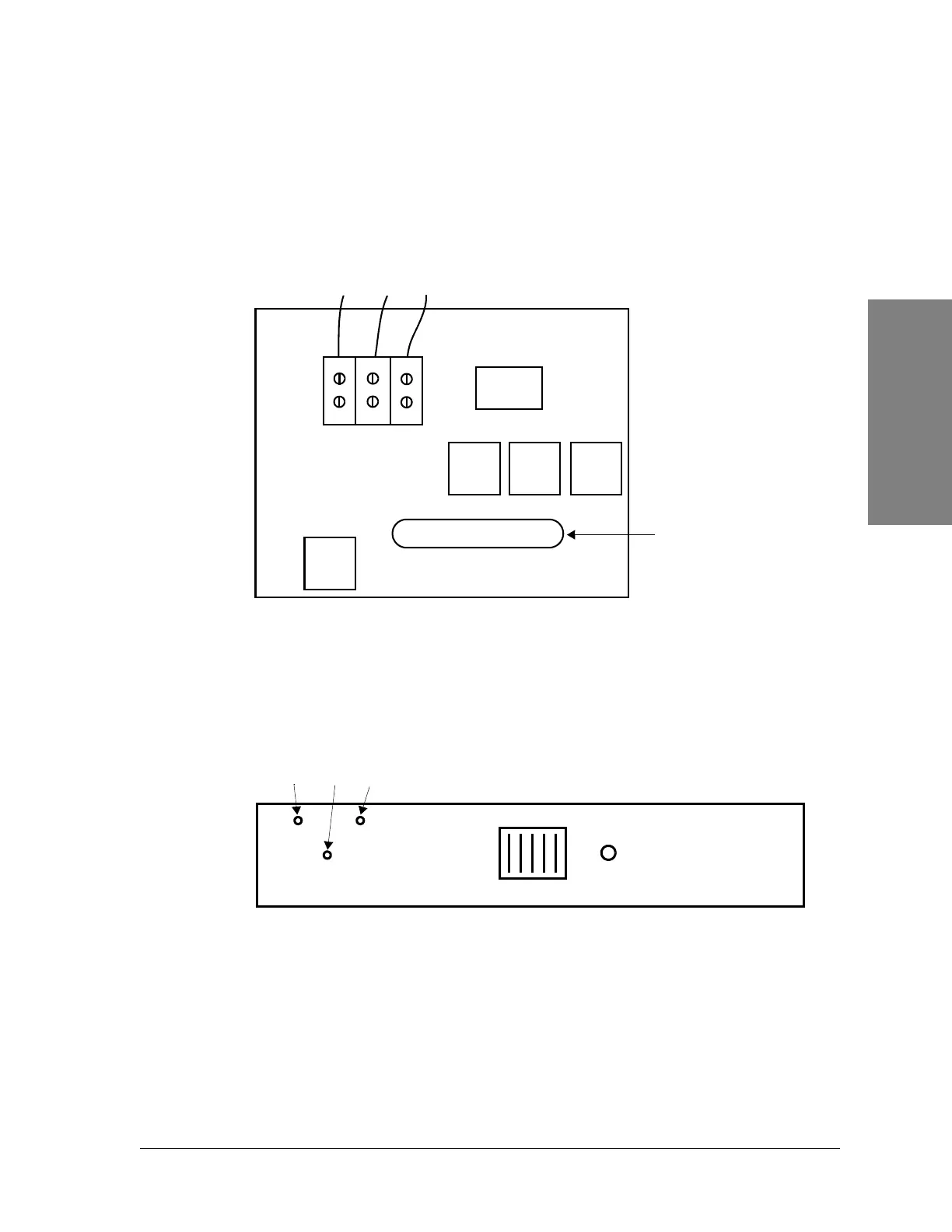
• See Figure 3-16 for wiring specifications.
• See Table 3-12 for recommended wiring sizes.
Figure 3-16: Constellation backplane, terminal
Repeater
Connect the wires to the quick disconnect tabs behind the Fuse Panel (Figure
3-17).
Figure 3-17: Fuse Panel, repeater
BAT A
BAT B
RET
24/48VDC
HARRIS Constellation Backplane
TO FUSE PANEL
ALARM I/O
Filter
Filter
Filter
Filter
26
1
25
50
Red
White
Black
J1
J2
External
alarm/control
connector
DC IN B
(P3)
DC IN A
(P6)
RETURN
(P2)
Red
White
Black
FUSE
ALARM