Harris Corporation Constellation™
Detailed Installation Procedures 3-15
INSTALLATION
AND
COMMISSIONING
Interconnection Cabling
DS1 Configuration
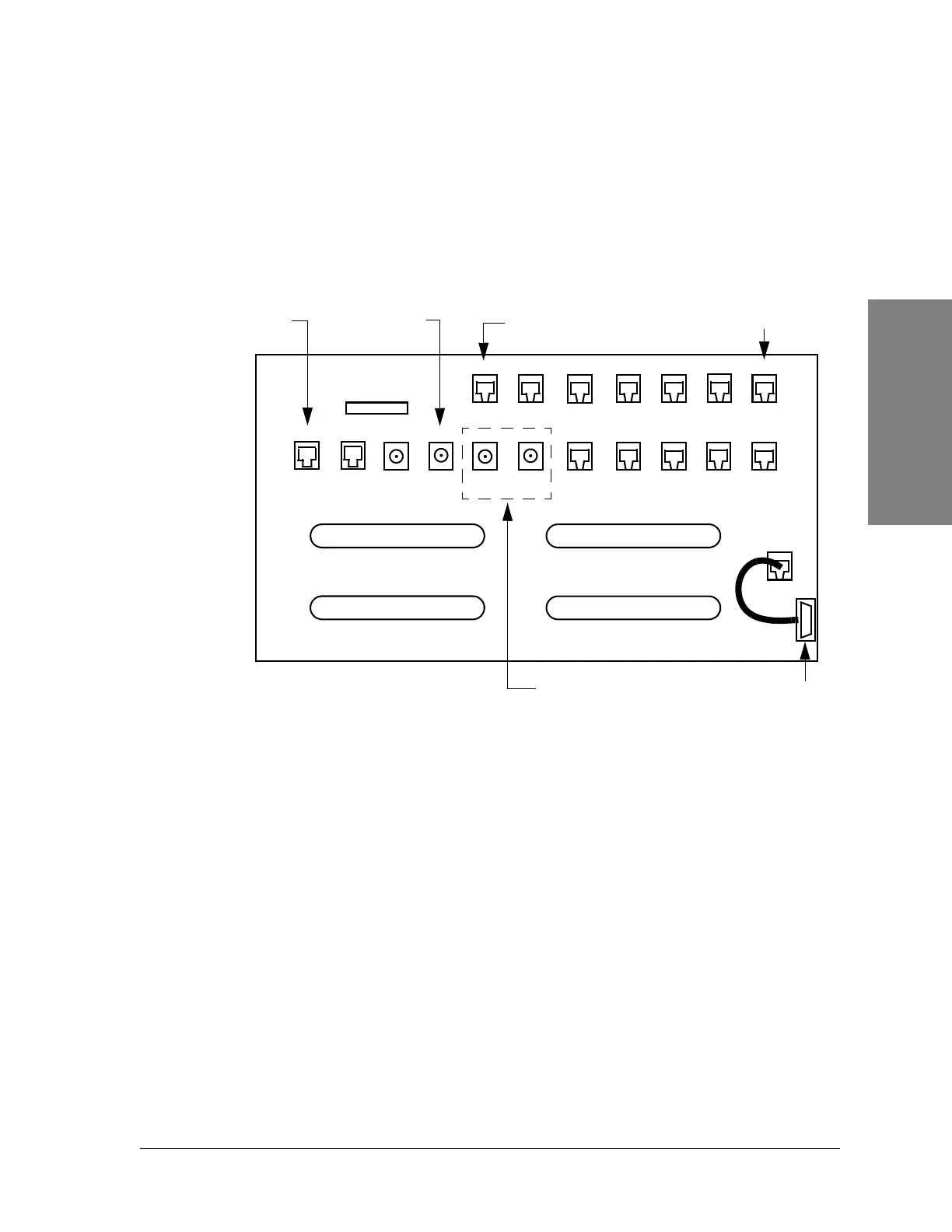
See Figure 3-6 and Table 3-8 for recommended interconnection cabling.
Figure 3-5: Customer access area
a. You may need to remove the Fan Assembly for easier installation of the
cables. See page 11-5 for instructions on how to remove the Fan
Assembly.
b. Install the cables through the right port hole of the card cage.
If the Fan Assembly was removed, reinstall the Fan Assembly. See page 11-7 for
instructions on how to install the Fan Assembly.
Wayside
Monitor
VersaT1lity
VF
Port 1
VF
Port 2
Wayside
Out
Wayside
In
Data
Port 2
DS3
Out
DS3
In
Handset 2
Handset 1
Aux
Ethernet
Spur
Keypad
Can
Fan
DS1 17-32 Out
DS1 1-16 In
DS1 17-32 In
DS1 1-16 Out
FSCAN
DE-9
RJ-45
T1 Wayside
1
E1 Wayside, SDH option only
RJ-11
26
25
26
25
25
25
26
26
1
1
1
1
50
50
50
50
BNC
Data
Port 1
Notes:
1. The wayside connection for T1 is not for 1xDS3 or 4xDS3 but only for OC-3,
3xDS3, and 2xDS3 +28xDS1.
2. DS1 In = Input to the radio from the customer’s DSX.
3. DS1 Out = Output from the radio to the customer’s DSX.
J16
J33
J17 J18
J31
J23
J24
J36
J25
J32
J35
J26
J27 J20
J21
J22
J15
J19
J28
J29
J30
P15
P14