Harris Corporation Constellation™
Radio Frequency Section 11-11
FIELD-
REPLACEABLE
UNITS
Ensure that the Multiplier-Filter you are installing
is the correct option.
4. Reverse the previous three steps to install the Multiplier-Filter onto the
Transmitter Assembly.
Removing and Installing the 100 MHz OCXO
1. Place the Transmitter Assembly on a flat surface.
2. Disconnect the MCX connector (J4) by carefully pulling it up straight from
the printed circuit board. The connector is designated
100MHz
on the
board. See
Figure 11-10
.
3. Disconnect the power connector from the printed circuit board.
4. Carefully pull out the 100 MHz OCXO from the Transmitter Assembly,
taking care not to remove the grommets from the printed circuit board.
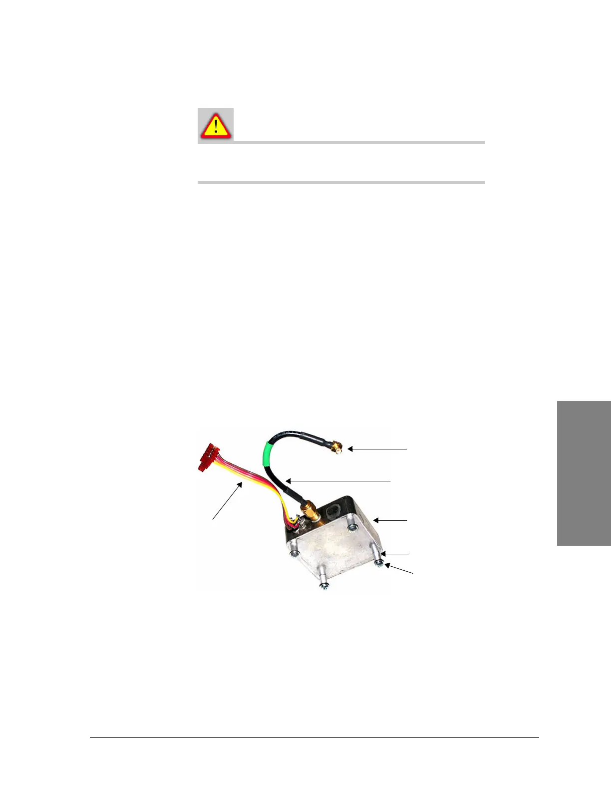
5. Remove the SMA cable from the OCXO you have just removed. See
Figure
11-11
.
Figure 11-11:100 MHz OCXO
6. Remove and retain the 4 SEMS Phillips screws, washers, and spacers from
the bottom of the OCXO.
7. Obtain a new 100 MHz OCXO.
8. Install the 4 spacers with the SEMS Phillips screws and washers you
removed in
step 6
onto the bottom of the new OCXO.
9. Connect the SMA cable you removed in
step 5
onto the 100 MHz OCXO. Do
not tighten.
SEMS Phillips screw
and washer (4)
100 MHz OCXO
Power cable
MCX connector
SMA cable
Spacer (4)