Harris Corporation Constellation™
Transmitter Frequency Measurement 8-11
ROUTINE
MAINTENANCE
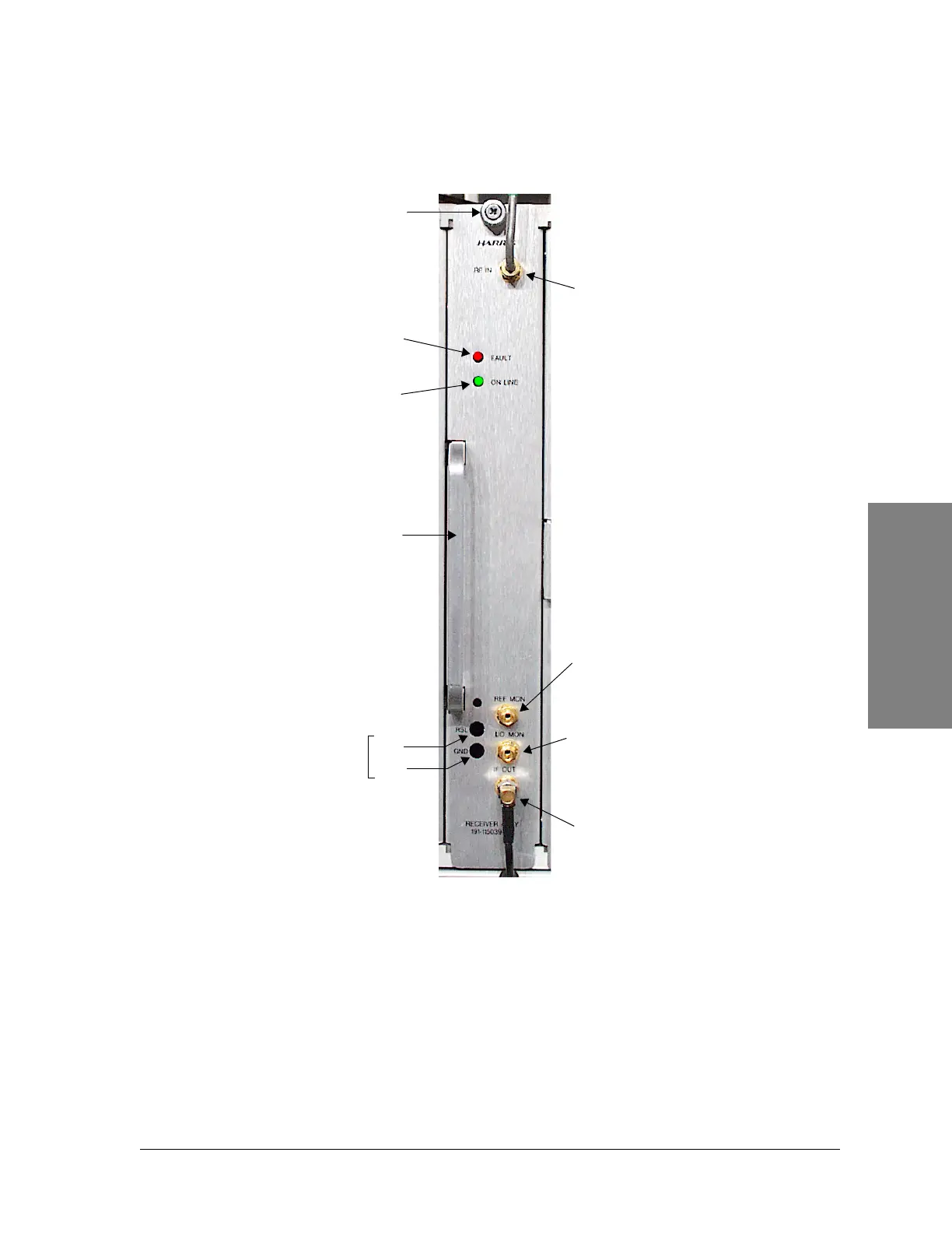
Figure 8-3: Receiver Assembly, front view
RSL Test Point
At -21 dBm or higher, a 10 dB attenuator is engaged, resulting in a 1 volt drop
(apparent 10 dB) in the RSL test point reading. The Keypad will display the
corrected (unattenuated) value. At nominally -23 dBm, the attenuator is
disengaged, and the meter will reflect the unattenuated value. See Figure 8-4.
Note: To prevent damage to
the connectors, do not
exceed 8 to 9 in-pounds of
torque.
RF IN (from ACU)
IF OUT (to Modem)
Thumb screw
REF MON
Reference frequency test
point (100 MHz)
Test points for
aligning the
antenna
(See page 8-11)
FAULT
(red LED)
ON LINE
(green LED)
RSL
GND
Handle
LO MON*
LO synthesizer test point
(2.060 to 2.160 GHz)
(For factory use only)