Harris Corporation Constellation™
Detailed Terminal Test 3-27
INSTALLATION
AND
COMMISSIONING
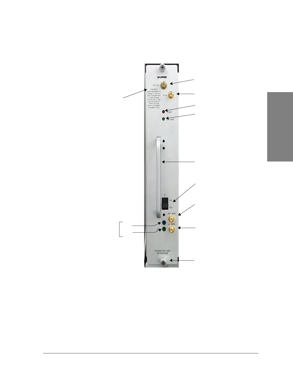
Figure 3-18: Transmitter Assembly, front view
Note: To prevent damage to
the connectors, do not
exceed 8 to 9 in-pounds of
torque.
IF IN (from Modem)
RF OUT (to ACU)
Thumb screw (2)
Transmitter
output level
LO MON
LO synthesizer test
point
(2.060 to 2.160 GHz)
(For factory use only)
REF MON
Reference frequency
test point
(100 MHz)
ON/OFF switch, turns the
power amplifier on or off
FAULT (red LED)
ON LINE (green LED)
TSL
GND
Handle
Caution: When measuring
Tx power at RF OUT, over
torquing may cause damage.
For on-line Tx, use monitor
port at front of ACU.
Refer to product
documentation.