2 Equipment Description
2.29 I/O Link Interface Address Pinning
R688 HPM High-Performance Process Manager Service 173
December 2020 Honeywell
IOP Only card file pinning location
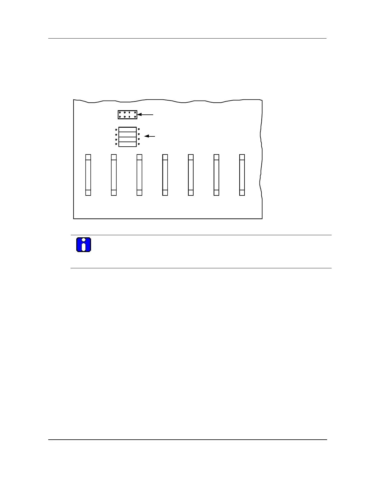
The following figure illustrates the location on the IOP Only card file backpanel where the I/O Link
Interface address is configured. The IOP Only card file may be part of the residual hardware from the
upgrade of a PM or APM subsystem to an HPM subsystem.
Figure 85 IOP Only Card File I/O Link Interface Address Pinning
ASSY NO. 51401406-10015 SIOM BACKPLANE
51572
1
25
SLOT 6
J21
26
50
I/O Link Address
(Zero-ohm Resistor Jumpers)
I/O Link Address
(Plug Jumpers)
1
25
SLOT 7
J22
26
50
R5
R8
R7
R6
1
2
4
P
P 4 2 1
1
25
SLOT 4
J19
26
50
1
25
SLOT 5
J20
26
50
1
25
SLOT 3
J18
26
50
1
25
SLOT 1
J16
26
50
1
25
SLOT 2
J17
26
50
ATTENTION
The numerical address displayed on the Operator Console displays is numbered one higher
than the actual configured binary address. The binary card file address of 0 is displayed as a
numerical address of 1 on the system displays.
Two pinning methods
A choice of two methods can be used to implement the I/O Link Interface addressing on the card file.
Plug jumpers
Zero-ohm resistor jumpers
One method only
One of the two methods must be disabled. Both cannot be active. Remove all jumpers and use the zero-
ohm resistors or clip out the zero-ohm resistors and use the jumpers. The jumper method (without the
resistors) is the most common method.

 Loading...