2 Equipment Description
2.27 EUCN Cable System
162 HPM High-Performance Process Manager Service R688
Honeywell December 2020
Control Firewall status indicators
Control Firewall Startup
The following table summarizes the stages the CF9 goes through after power is applied to its IOTA
during startup. The CF9 repeats these stages every time power is cycled Off/On or the pins on its reset
pad are shorted.
Power Light Emitting Diode (LED) lights (green)
Status LED is red while the CF9 runs its power-on self test (POST).
When the CF9 POST completes, the Status LED turns green and the FTE
port LEDs blink green and off for all connected ports when there is traffic, and
remain steady green for connected ports when there is no traffic. The LEDs
for unconnected FTE ports are off.
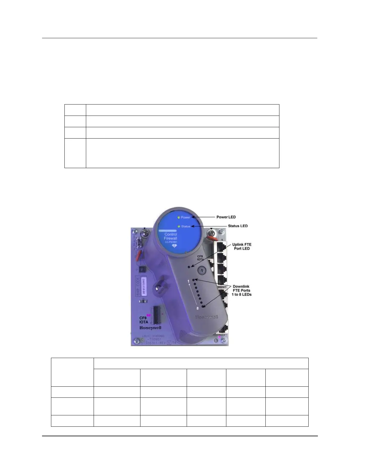
CF9 LED Descriptions
The following illustration and table identify and describe the indications associated with the LEDs on the
CF9.

 Loading...