7 IOP Calibration Procedures
7.8 Redundant AO IOP Calibration Procedure
R688 HPM High-Performance Process Manager Service 451
December 2020 Honeywell
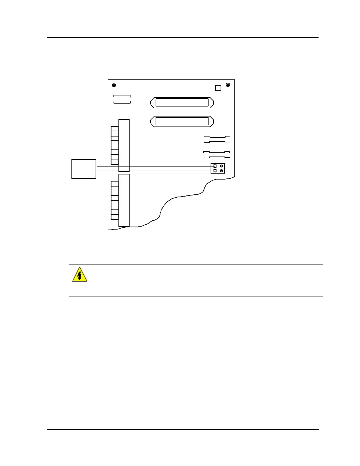
The following figure is an illustration of the redundant Analog Output FTA connections necessary to
calibrate an Analog Output IOP.
Figure 218 Nonredundant AO Calibration FTA Connections
J2
ANALOG OUTPUT MU - TAOXO2
TERMINATION ASSY. NO. 51304476 - 100 REV A
CAL
S1
TB1
J1
+
-
Voltage
Source
+ CH
- 1
+ CH
- 2
+ CH
- 3
+ CH
- 4
STANDBY MANUAL CONNECTOR
1 AMP
F1
FTA CONNECTOR
1 AMP
F2
1 (+)
2 (–)
1
2
3
4
5
6
7
8
9
10
11
12
13
14
15
16
+ CH
- 5
+ CH
- 6
+ CH
- 7
+ CH
- 8
7.8 Redundant AO IOP Calibration Procedure
SHOCK HAZARD
Troubleshooting, opening this equipment and removing any panels or covers will expose the
user to the risk of a shock hazard. There are no user serviceable parts inside this equipment.
Refer all servicing only to qualified service personnel.
Simultaneous IOP calibration
Follow the Analog Output FTA calibration procedure in subsection “Nonredundant AO IOP Calibration
Procedure” (“IOP Calibration Procedures” section) to simultaneously calibrate both IOPs. The
calibration voltage source must be connected to both sets of calibration terminals on the redundant model
FTA simultaneously with parallel wiring as shown in the following figure. Refer to the Process Manager
I/O Installation manual for the assembly layout and calibration terminal locations for the model
MU-TAOX12, MU-TAOX52, MU-GAOX12, or MU-GAOX82 FTAs.

 Loading...