EasyManuals Logo
Home>Honeywell>Network Hardware>HPM

Honeywell HPM User Manual

Honeywell HPM
498 pages
To Next Page IconTo Next Page
To Previous Page IconTo Previous Page
Page #441 background imageLoading...
Page #441 background image
7 IOP Calibration Procedures
7.4 LLAI IOP Calibration Procedure
R688 HPM High-Performance Process Manager Service 441
December 2020 Honeywell
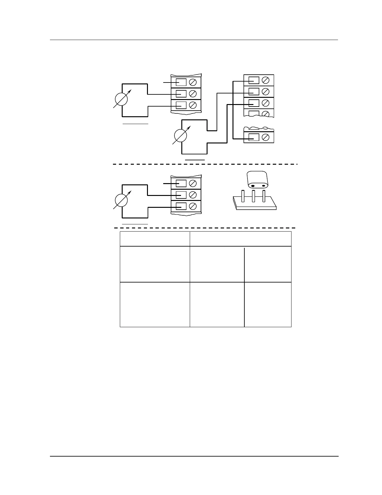
Figure 211 Full Scale Calibration Circuit – TC and All Linear Full Scale Circuits
NC A
B
C
A
B
C
+
+
User Input Device
Input Voltage:
Current Input:
0-100 mVdc
0-5 volt
4-20 mA
10-50 mA
100 mV
5 V
20 mA (5 V)
50 mA (5 V)
N/A
N/A
N/A
N/A
Themocouple:
ANSI J
ANSI K
ANSI E
ANSI T
ANSI B
ANSI S
ANSI R
Japanese Type R
40 mV
40 mV
40 mV
40 mV
20 mV
20 mV
20 mV
20 mV
100 mV
40 mV
100 mV
40 mV
20 mV
20 mV
20 mV
20 mV
Full-Scale Calibration Values
Normal Range Extended Range
Channels 2-8
Channel 1
-
-
TB1
TB2
17
1
2
3
4
Shield
Reference
Cu
Cu
Cu
Cu
Model MU/MC-TAIL01 and MU/MC-TAIL02 FTAs
NC A
B
C
+
-
Cu
Cu
Model MU/MC-TAIL03 FTA
Channels 1-8
1 3
Install the jumper between pins 2 and 3.
2
P1
Use copper (Cu) wire from voltage source.

Table of Contents

Questions and Answers:

Question and Answer IconNeed help?

Do you have a question about the Honeywell HPM and is the answer not in the manual?

Honeywell HPM Specifications

General IconGeneral
BrandHoneywell
ModelHPM
CategoryNetwork Hardware
LanguageEnglish

Related product manuals