2 Equipment Description
2.15 Power Systems
R688 HPM High-Performance Process Manager Service 91
December 2020 Honeywell
Early production Standard Power System
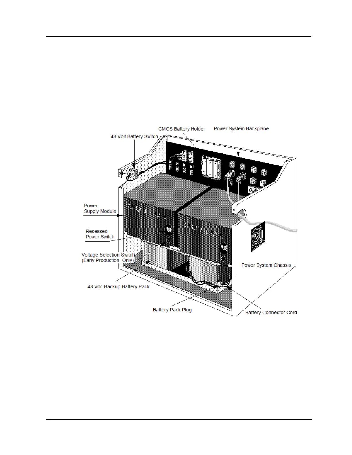
Figure 27 is an illustration of the early production Standard Power System. The Power System’s
connectors, terminal strips, battery and fuse holders are an integral part of the Power System backpanel.
There are eight 24 Vdc power distribution output connectors, four Cabinet Fan Assembly power
connectors with associated fuse holders, and a NiCad battery holder on the backpanel. Sets of terminals
provide alarm signals for each Power Supply Module and the CMOS Battery Backup.
The Power Supply Module in the later production Power System adjusts automatically to the input ac
voltage.
Figure 27 Standard Power System

 Loading...