2 Equipment Description
2.13 Field Termination Assembly
78 HPM High-Performance Process Manager Service R688
Honeywell December 2020
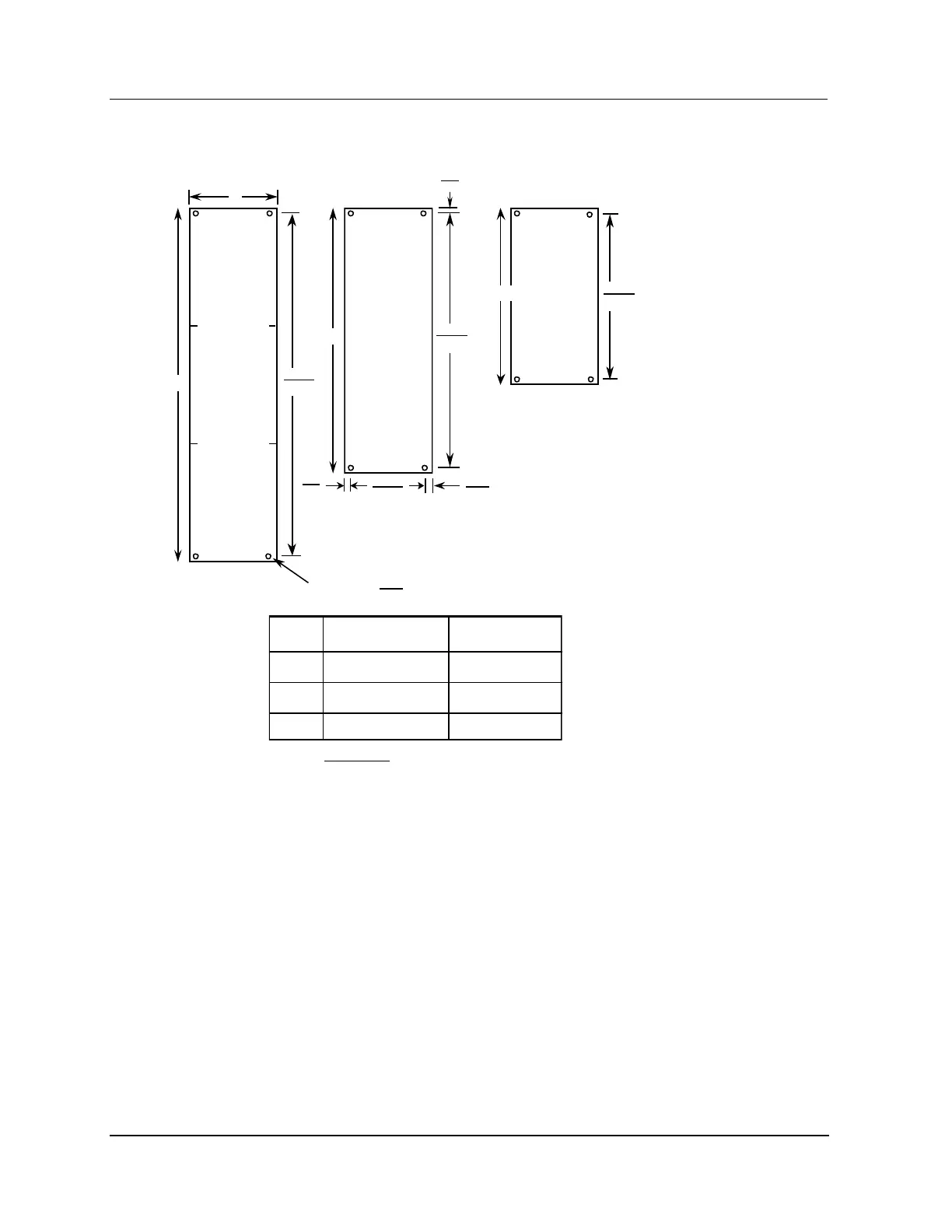
Figure 17 Field Termination Assembly (FTA) Sizes
C
Size
FTA
Hole Size = 3.96
.156
A
B
C
152.4/6.00
307.3/12.10
462.3/18.20
120.7/4.75
120.7/4.75
120.7/4.75
W
B
Size
FTA
L
10.8
.425
A
Size
FTA
L
Length L Width WSize
L
5.7
0.225
104.2
4.10
5.1
0.20
All measurements are in:
millimeters
inches
Note:
The center of the mounting holes is a constant distance from the edge of the
assembly board for all three FTA sizes as shown for size B.
Sizes B and C, depending on the type of FTA, can have additional mounting holes
along the length (sides) of the FTA. The additional mounting holes all fall on a grid
established for mounting adjacent A-size FTAs.
297.2
11.70
142.2
5.60
17.8
452.1
FTA Mounting Channels
The FTAs are installed at the rear or front of a dual access cabinet on one or more FTA Mounting
Channels. In a single access cabinet, the FTAs are mounted on FTA Mounting Channels at the front of
the cabinet. The FTA Mounting Channels also function as cable and wiring channels, or troughs. The
standard and Galvanically Isolated FTAs must not be mounted on the same FTA Mounting Channel.
Mounting both types of FTAs on the same FTA Mounting Channel is an intrinsic safety violation
because their field wiring will be routed together.

 Loading...