4 Fault Isolation
4.3 Fault Isolation Concepts
306 HPM High-Performance Process Manager Service R688
Honeywell December 2020
Troubleshooting Flow Chart
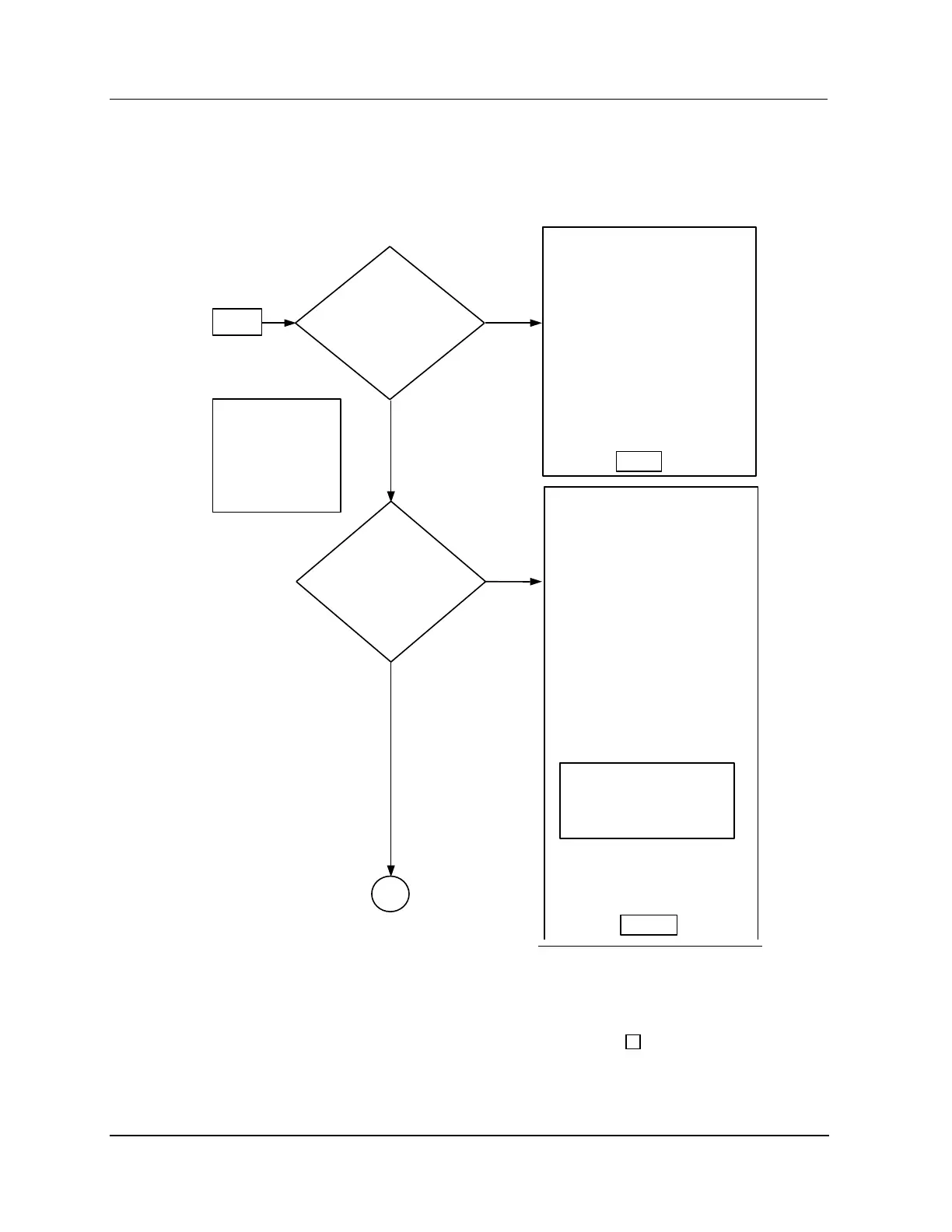
Fault isolation flowchart (Sheet 1 of 6)
Figure 180 HPM Fault Isolation Flowchart (Sheet 1 of 6)
The Indicators on the cards in the
HPMM and IOP card files. Refer to
“FTA indicator functions “ for
the
indicator functions. Replace the
The Power System dc voltages.
The ac input voltage and the
input wiring at the Power System.
The dc power cables to the HPMM
and IOP card files, and connectors
at the individual card files.
The voltages at the backplanes of
The Power and Status indicators
on the Comm/Ctrl card, I/O Link
card, and the UCN Interface
module. Reference Table 4-8.
Also check the alphanumeric
display on the Comm/Ctrl card.
Reference Tables 4-9 to 4-21.
Replace the cards as necessary.
The UCN drop cable connections
at the HPMM card file(s).
If any other HPMs on the same
UCN do not respond to operator
cable connections to the NIM.
After the fault has been corrected,
test the UCN using the UCN
Exerciser. Refer to “UCN Exerciser”
Section 5 for a
Section for a description of this test
program.

 Loading...