6 Removal and Replacement
6.5 AO Standby Manual Device Operation
412 HPM High-Performance Process Manager Service R688
Honeywell December 2020
Compact Analog Output Standby Manual device
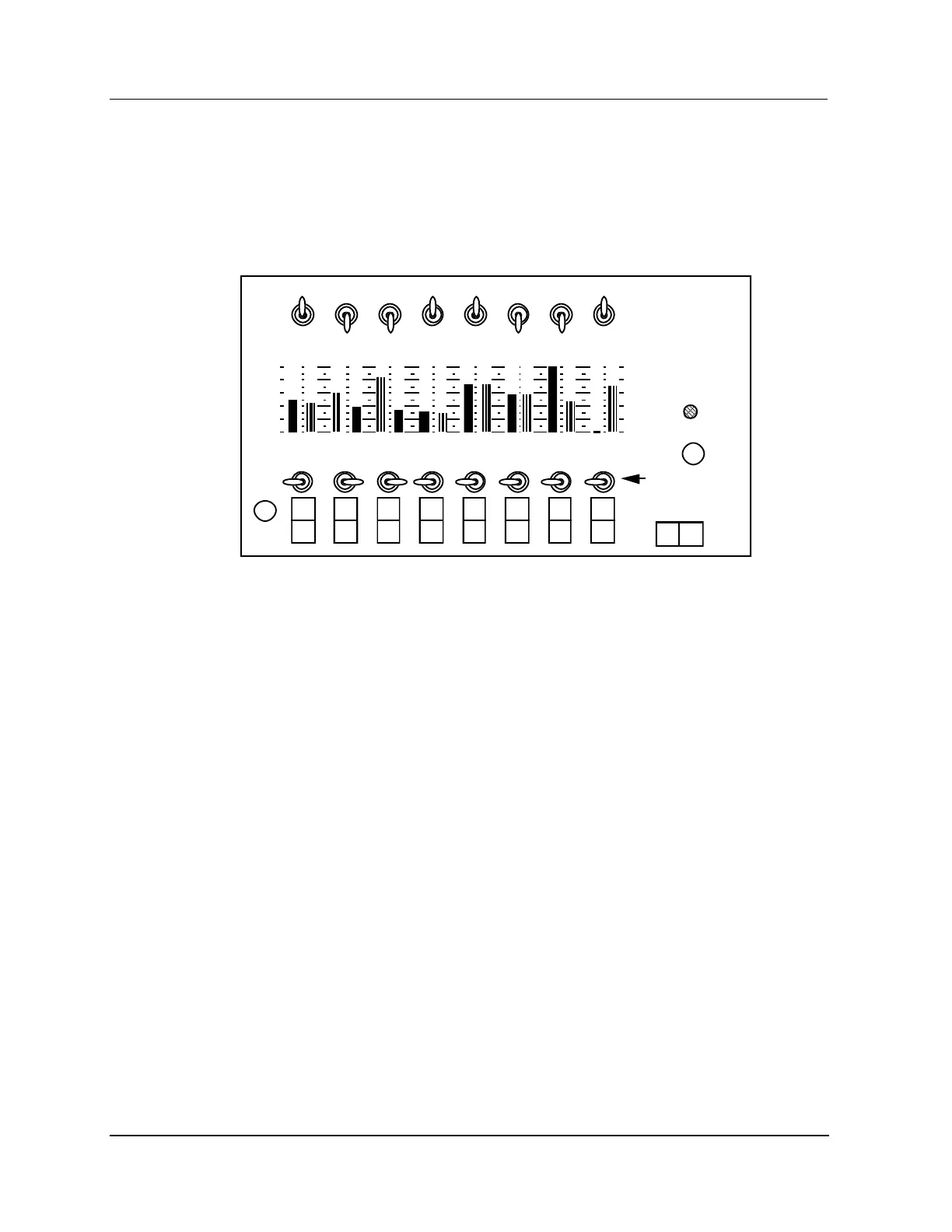
The compact Analog Output Standby Manual (AOSM) device display panel, as shown in the following
figure, monitors the outputs of an Analog Output (AO) IOP as well as the AOSM itself, presenting their
output values on the display panel as a percentage of the range. It can be ordered by Honeywell part
number 51401926-100.
Figure 203 Compact Analog Output Standby Manual Device
Features
The Analog Output Standby Manual device has the following features.
The Analog Output Standby Manual device will accept the standard IOP to FTA cables with either
DIN or phone type connectors.
The Analog Output Standby Manual device can be powered by any of two methods.
The HPM card file backpanel through its connection to the STANDBY MANUAL connector on
the FTA.
By applying 110 or 220 Vac to connector at the side of the AOSM. The universal power supply
in the AOSM will accept 100 to 240 Vac, 50/60 Hz.
The panel display shows the 4-20 milliamp current levels in a 0% to 100% scale for all eight IOP
outputs as well as the level of all eight AOSM outputs.
The toggle switches are a “tamper-proof” style that require the operator to lift up on the bat handle
before changing the switch position.
The compact AOSM’s output current and the its OUTPUT SOURCE SELECT switches are
disabled when the device is first connected to the FTA, the STANDBY ENABLE indicator is
extinguished, or the cable to the FTA is disconnected.
When the AOSM is enabled by depressing the STANDBY ENABLE switch, the STANDBY
ENABLE indicator is illuminated and the OUTPUT SOURCE SELECT switch settings are
active.
The balancing of the AOSM output values to equal the IOP output values is performed
automatically, either continuously, or by single snapshot action. Balancing in the other direction,
IOP to AOSM, is an operator function.
A DIR/REV switch for each channel flips the display and reverses the INC/DEC action relative to
the actual current level. In the DIR position, 4 mA equals 0% and 20 mA equals 100%. The INC
position of the INC/DEC switch will increase current and the DEC position will decrease current.

 Loading...