Indicates that power is present on the FTA.
One of the following indicator status conditions exists. The conditions are listed in
the order of importance.
Not lit: This condition exists only when the FTA is in a Hard failure state.
Slow blink: This condition indicates that the FTA has not (Symmetrical 1 sec.
blink) received a Time Out Gate (TOG) refresh from the SI IOP within 10
seconds.
Fast blink: This condition indicates that one or more Array (Symmetrical .5 sec.
blink) Points configured for this FTA have a communications error.
Odd blink: This condition indicates that one or more Array (Asymmetrical 1/.25
sec. blink) Points configured for this FTA have an error in the Array Point
configuration error category.
The IOP/HPMM is not configured or configured improperly.
Constantly lit: This condition indicates that no errors exist in the FTA.
Due to the long ACK/Message timeout time and the required three tries, the FTA
may indicate a TOG timeout if the CIM is responding with an ACK to the FTA
requests, or if the destination PLC device is not responding to the requests.
Additional troubleshooting information can be found in the Serial Interface
Options manual.
SHOCK HAZARD
Troubleshooting, opening this equipment and removing any panels or covers
will expose the user to the risk of a shock hazard. There are no user
serviceable parts inside this equipment. Refer all servicing only to qualified
service personnel.
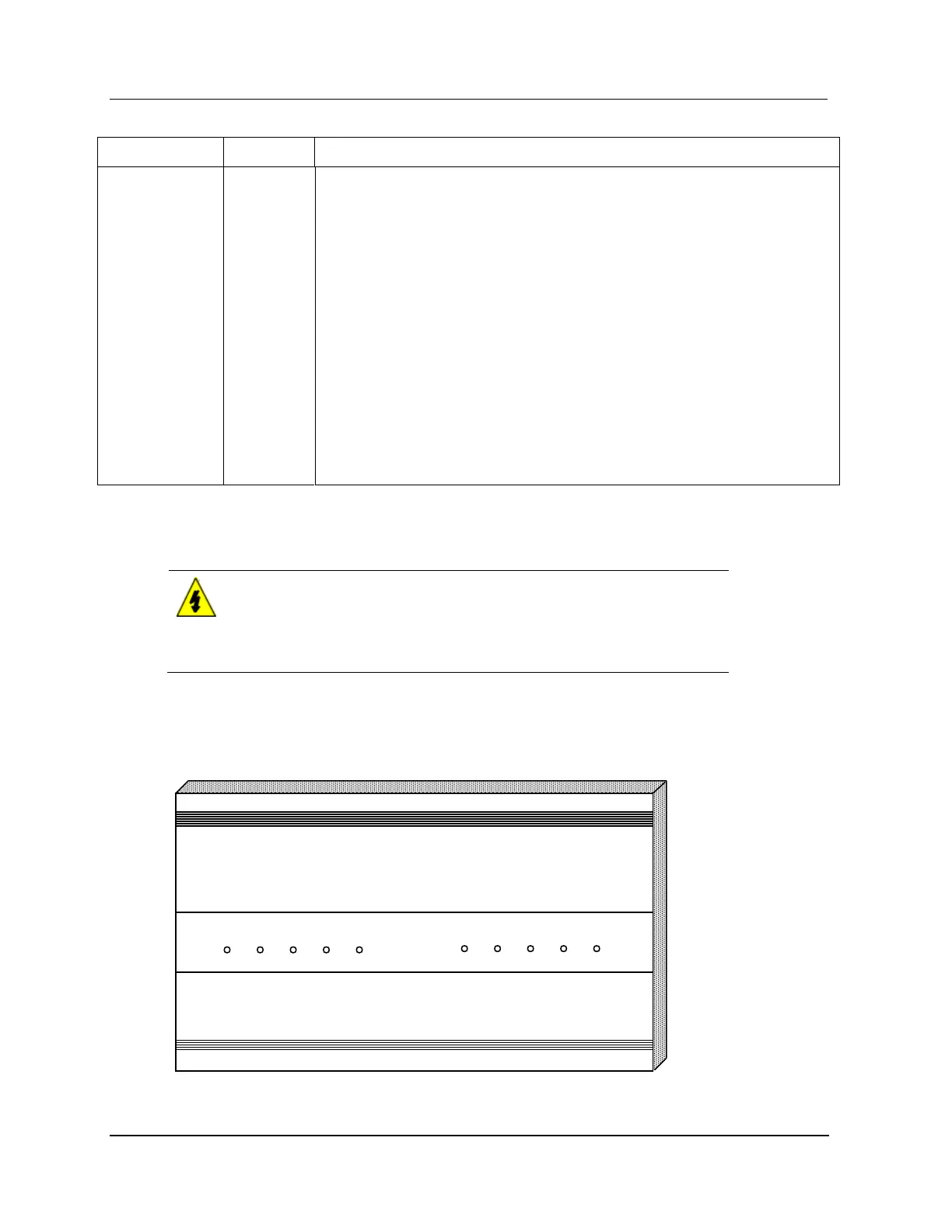
Examine the DC Out, Battery, Fan/Temp, AC In, and Charging indicators for each Standard Power
Supply module. The Standard Power System cover, illustrated by the following figure, identifies the
LED indicators. If the Power system is fully functional, all five of the indicators are Illuminated.
Figure 186 Standard Power System Indicators

 Loading...