2 Equipment Description
2.16 Power Distribution
98 HPM High-Performance Process Manager Service R688
Honeywell December 2020
HPM Standard Power System
Refer to Figure 32 for the location of the CMOS Battery Backup Assembly mating connector on the
backpanel.
The Standard Power System configuration has NiCad batteries located at the upper left of the Power
System chassis backpanel, and the supporting CMOS Battery Backup Assembly is inserted into a
connector at the lower right-hand side of the backpanel. The right Power Supply Module must be
removed to view the assembly. The assembly provides both charging circuitry and a monitoring circuitry
for failure alarm reporting. The new version (CMOS Battery Backup Assembly) is backward compatible
with the early production version. The older version is not forward compatible.
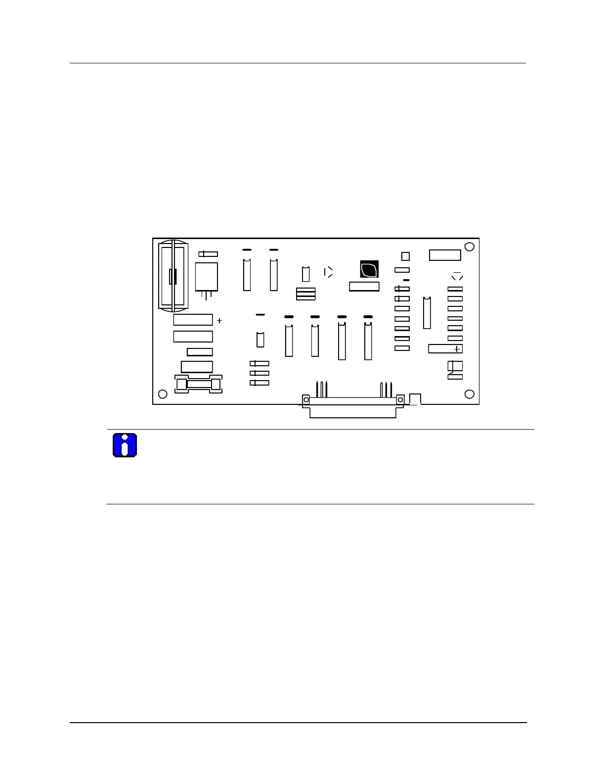
See the following figure for an illustration of the latest version of CMOS Battery Backup Assembly.
Figure 34 CMOS Battery Backup Assembly (HPM Standard Power System)
ATTENTION
A bad batteries alarm occurs when the CMOS batteries are discharged or when a
High-Performance Comm/Control card is not present in an HPMM card file with or without
power applied to the card file. Both the High-Performance Comm/Control and the
High-Performance I/O Link cards must either be present or absent in order to charge the
batteries.
AC Only Power System
The AC Only Power System uses alkaline batteries which must be replaced frequently. The three alkaline
batteries are located at the center of the AC/DC Distribution Assembly as shown in Figure 29. No
charging circuitry or monitoring circuitry for failure alarm reporting exists.
A new set of batteries will provide approximately 55 hours of backup time.

 Loading...