7 IOP Calibration Procedures
7.5 Nonredundant HLAI IOP Calibration Procedure
R688 HPM High-Performance Process Manager Service 447
December 2020 Honeywell
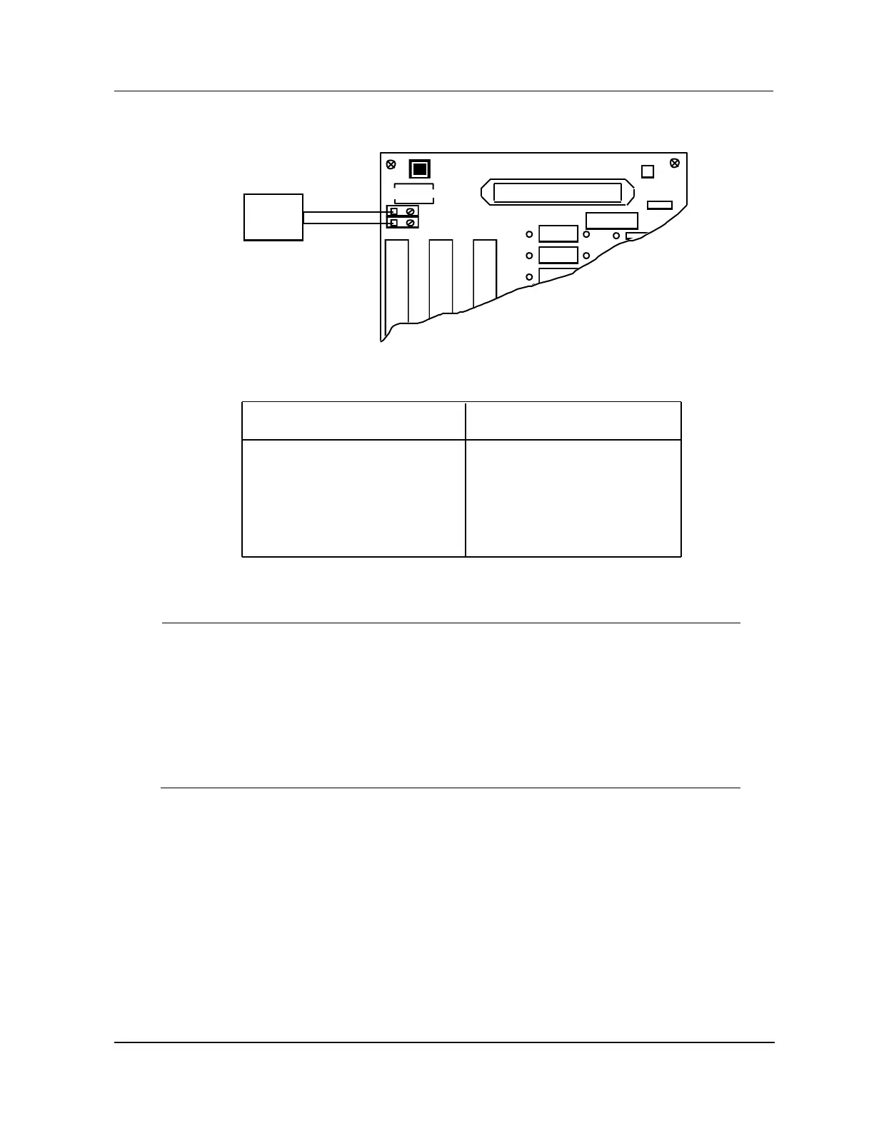
Figure 216 Nonredundant HLAI Calibration Connections
User Input Device
Voltage Input:
Current Input:
0-5 volt
1-5 volt
4-20 mA
10-50 mA
5 V
5 V
VCAL Voltage Source
H
R3
ANALOG INPUT HIGH LEVEL /SF1 INPUT MU - TAIHO2
TERMINATION ASSY. NO. 51304453 - 100 REV
B
CAL
S1
1 (+)
2 (-)
TB1 TB2 TB3
VCAL
J1
DATE CODE
+24 V
R1
R2
+
-
Voltage
Source
5 V
5 V
T
B
4
Short the two calibration pads at the upper-left corner of the HLAI FTA as shown in
Figure 215 to start the calibration. For the Galvanically Isolated FTAs, two pins in the
Marshalling Panel connector are shorted together.
Ensure that the calibration target on the HLAI Detail Status display has changed back
to ENABLE CALIBRATION, indicating that the zero and span calibration process has
completed. Check for the Soft failure CALIB ABORT, which indicates bad calibration.
Disconnect the calibration voltage source wiring.
Inform the operator that the HLAI can be returned to on-line operation.

 Loading...