6 Removal and Replacement
6.6 DO Standby Manual Device Operation
416 HPM High-Performance Process Manager Service R688
Honeywell December 2020
Standby Manual device control procedure
Use the HPM Status display to save a Checkpoint for the IOP(s), if desired, and then use the following
procedure to provide Standby Manual device control of the FTA field devices.
Place ENABLE STANDBY switch on the Digital Output Standby Manual device in the
OFF position.
Connect the Digital Output Standby Manual device cable to the FTA CABLE B
connector, J2, on the Digital Output FTA.
When the Digital Output Standby Manual device is connected to the connector on the
Digital Output FTA, all "on" IOP outputs light their corresponding indicator on the Digital
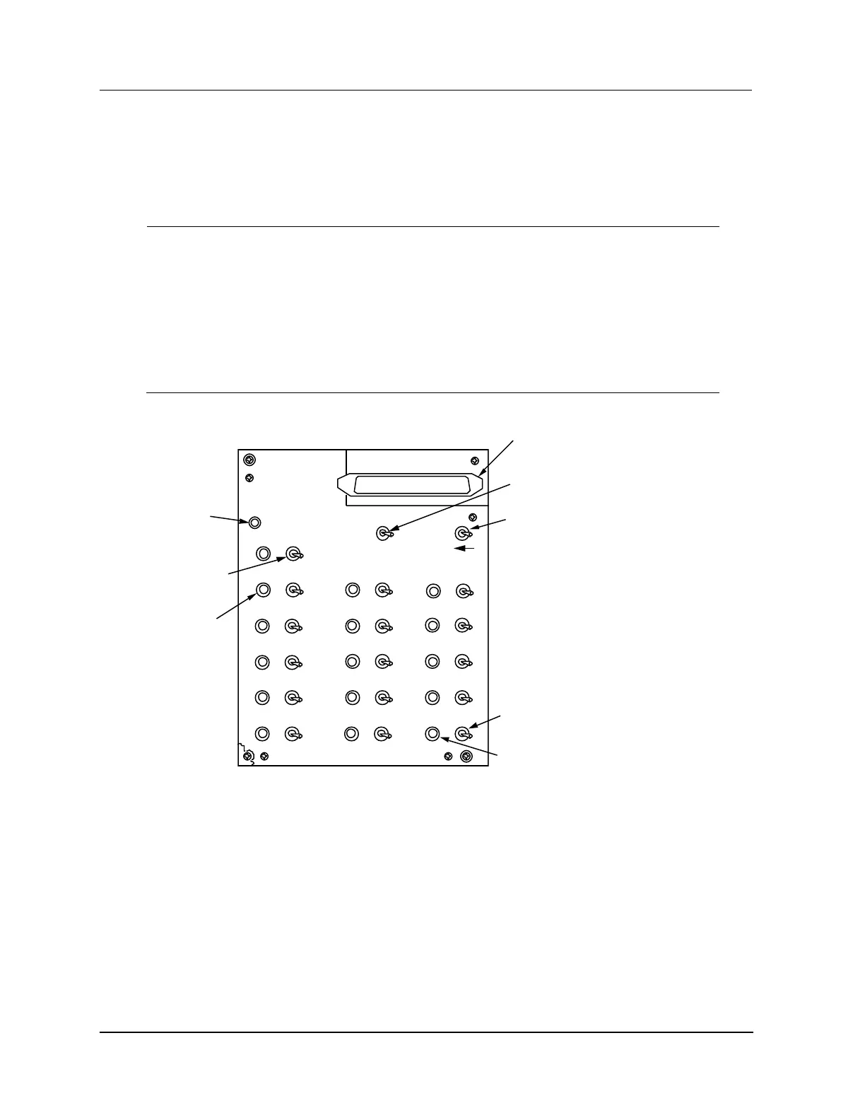
Output Standby Manual device. See Figure 205 for an illustration of the model MU-
SMDX02 Digital Output Standby Manual device panel. If you only want to display
outputs, stop at this point.
Figure 205 Digital Standby Manual Device Panel
HO NEYWELL
DIGITAL OUTPUT
ST ANDBY MANUAL
ASSEMBLY NO .
51304527-100
ST ANDBY
ACTIVA TED
ENAB LE
ST ANDBY
ACTIVA TE
ST ANDBY
OF FON
ON
OF FON
OUT 1
OF FON
OUT 2
OF FON
OUT 3
OF FON
OUT 4
OF FON
OUT 5
OF F
ON
OUT 6
OF FON
OUT 7
OF FON
OUT 8
OF FON
OUT 9
OF FON
OUT 10
OF FON
OUT 11
OF FON
OUT 15
OF F
ON
OUT 14
OF FON
OUT 13
OF F
ON
OUT 12
OF FON
OUT 16
Standby
Activated
LED
Enable Standby
Switch
Activate Standby
Switch (Mom entary)
Output 16
Control Switch
Output 16
LED Indicator
Output 1
Control Switch
Output 2
LED Indicator
DO FTA Cable
Connector
Note:
The Digital Output Standby Manual device is designed to install on
an FTA Mounting Channel, but it can be installed elsewhere.

 Loading...