7 IOP Calibration Procedures
7.4 LLAI IOP Calibration Procedure
444 HPM High-Performance Process Manager Service R688
Honeywell December 2020
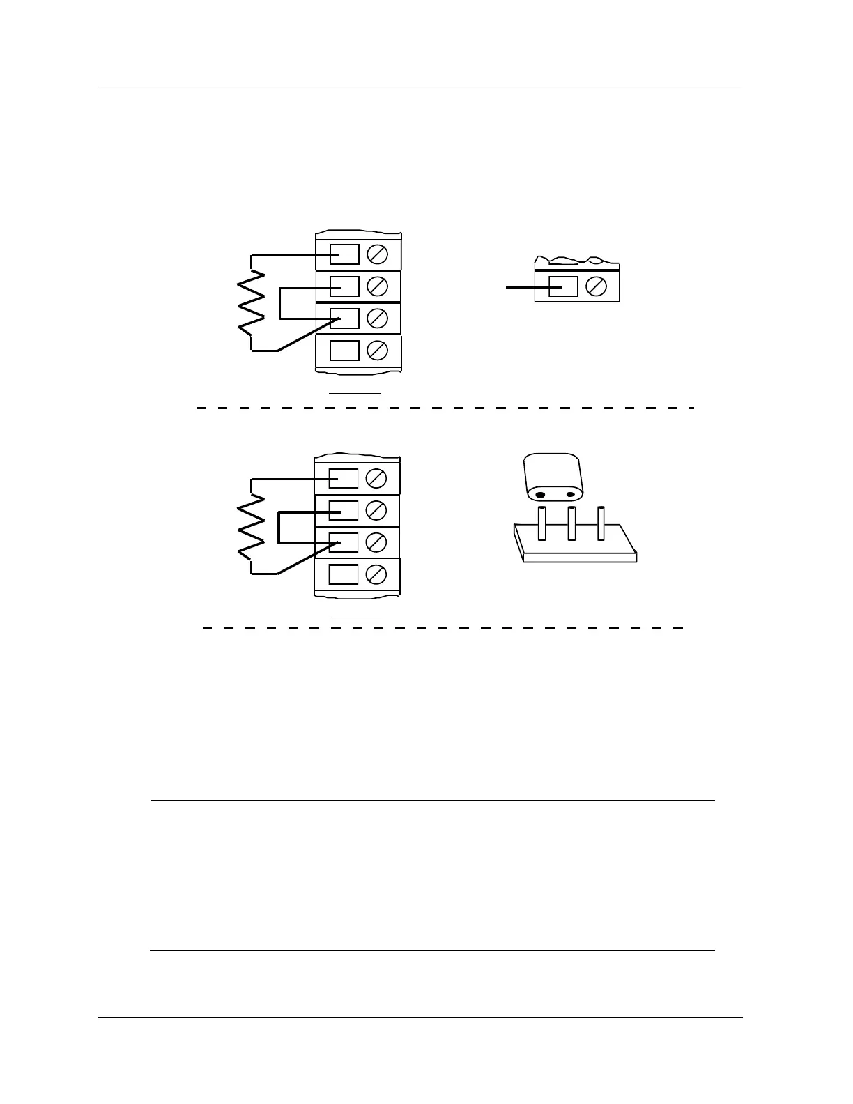
RJ calibration circuit for RJ full scale
Figure 214 RJ Calibration Circuit – RJ Full Scale
Be sure there is one wire connected to the "A" terminal and one wire connected to the "B" terminal.
There s hould be two wiresconnected to the "C" term inal.
Calibrate any time the thermocouple is done calibrated.
R cal = 2 kohm precision resistor. Be sure the connection is made to only the terminals for channel 1.
Note:
A
B
C
Shield
Model MU/MC-TAIL01 and MU/MC-TAIL02 FTAs
Model MU/MC-TAIL03 FTA
A
B
C
Shield
1 3
Install the jumper between pins 1 and 2.
2
P1
NC
17
TB2
Remove the wire between
TB-1 and TB2-17.
R cal
R cal
Reference
TB1
Channel 1
TB1
Channel 1
1
2
3
4
1
2
3
4
2487
Ensure that the calibration target on the LLAI Detail Status display has changed back to
ENABLE CALIBRATION, indicating that the zero and span calibration process has
completed.
Check the LLAI IOP card for Soft failures. If a Soft failure occurred, find the source of
the failure, correct it, and repeat the calibration procedure. If none occurred, remove
the test equipment from the FTA and reconnect the field wiring. If the FTA has screw
terminal strips, replace the plastic cover over the strips.
Inform the operator that the LLAI subsystem can be returned to on-line operation.

 Loading...