6 Removal and Replacement
6.6 DO Standby Manual Device Operation
R688 HPM High-Performance Process Manager Service 415
December 2020 Honeywell
Connection
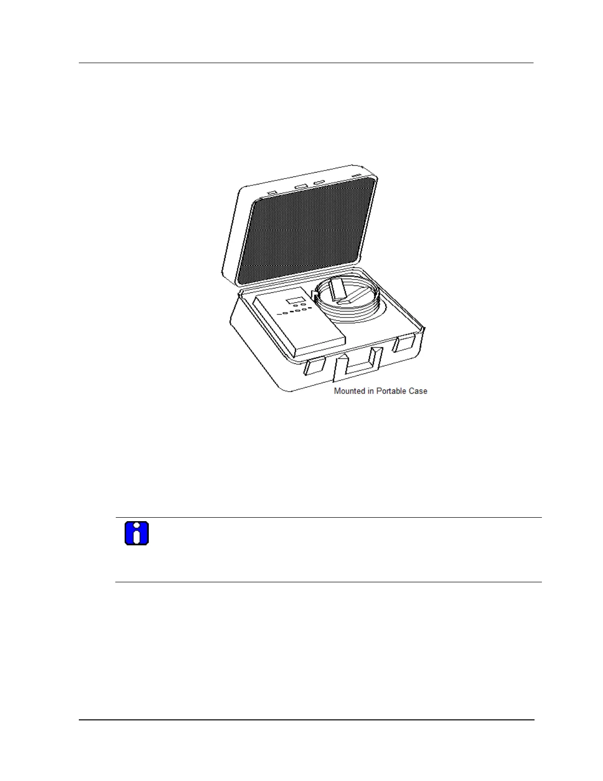
Connection of the Digital Output Standby Manual device to the FTA Standby connector is made with a
standard IOP to FTA cable. A 3-meter cable is included with the model MU-SMDC02 Digital Output
Standby Manual device that is shown in the following figure.
Figure 204 Model MU-SMDC02 Portable Digital Output Standby Manual Device
Output control switches disablement
The Digital Output Standby Manual device’s output control switches are disabled when the DOSM is
first connected to the FTA, or whenever the ENABLE STANDBY switch on the DOSM is in the OFF
position.
Switch activation
When the ENABLE STANDBY switch is in the ON position, momentary operation of the ACTIVATE
STANDBY switch latches the manual mode of the Digital Output Standby Manual device and activates
the 16 output switches to control the FTA as discussed below.
ATTENTION
The IOP to FTA cable, from the card file backpanel to the FTA, must be connected to carry the
+24 Vdc and the common from the IOP backpanel to the FTA and the Digital Output Standby
Manual device. Also, the Digital Output Standby Manual device cannot be used with the 24 Vdc
nonisolated Digital Output FTA if the FTA load voltage for any output is other than +24 Vdc.

 Loading...