2 Equipment Description
2.29 I/O Link Interface Address Pinning
174 HPM High-Performance Process Manager Service R688
Honeywell December 2020
Jumper method example
I/O Link Interface address configuration using plug jumpers is demonstrated with the following example.
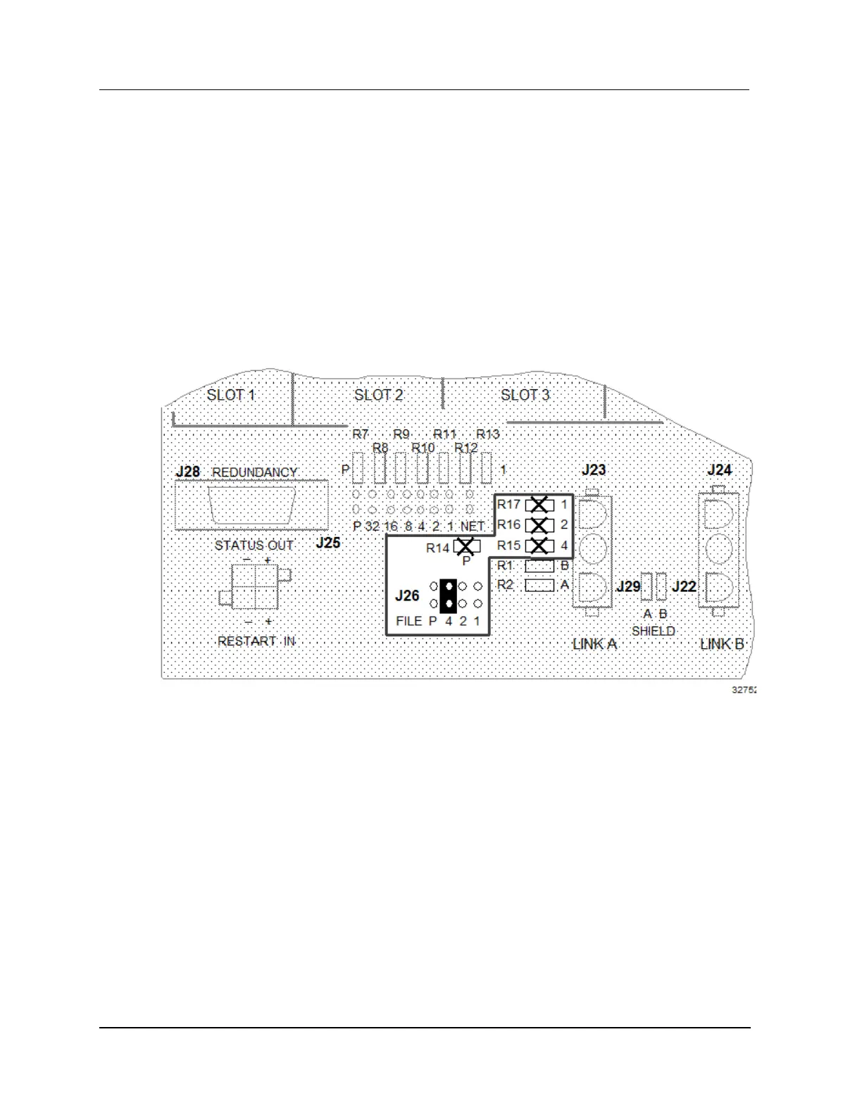
Refer to Figure 86 to locate the card file pinning area (J26) in the following discussion.
Assume an I/O card file is to be configured for an I/O Link Interface hardware address of 4. The
Operator Console will display this card file’s I/O Link Interface address as 5. Take diagonal cutters and
remove all the zero-ohm resistors. Install a plug jumper to bridge both pins at position 4. Because this
single jumper constitutes an odd number of jumpers, remove the P (parity) plug jumper as well as all
others.
Even though the J-number (J26 in this case) differs between the 7-Slot and 15-Slot card files, the method
of pinning the card file address remains the same.
Figure 86 Left 7-Slot Card File I/O Link Interface Address Pinning with Plug Jumpers

 Loading...