7 IOP Calibration Procedures
7.4 LLAI IOP Calibration Procedure
R688 HPM High-Performance Process Manager Service 439
December 2020 Honeywell
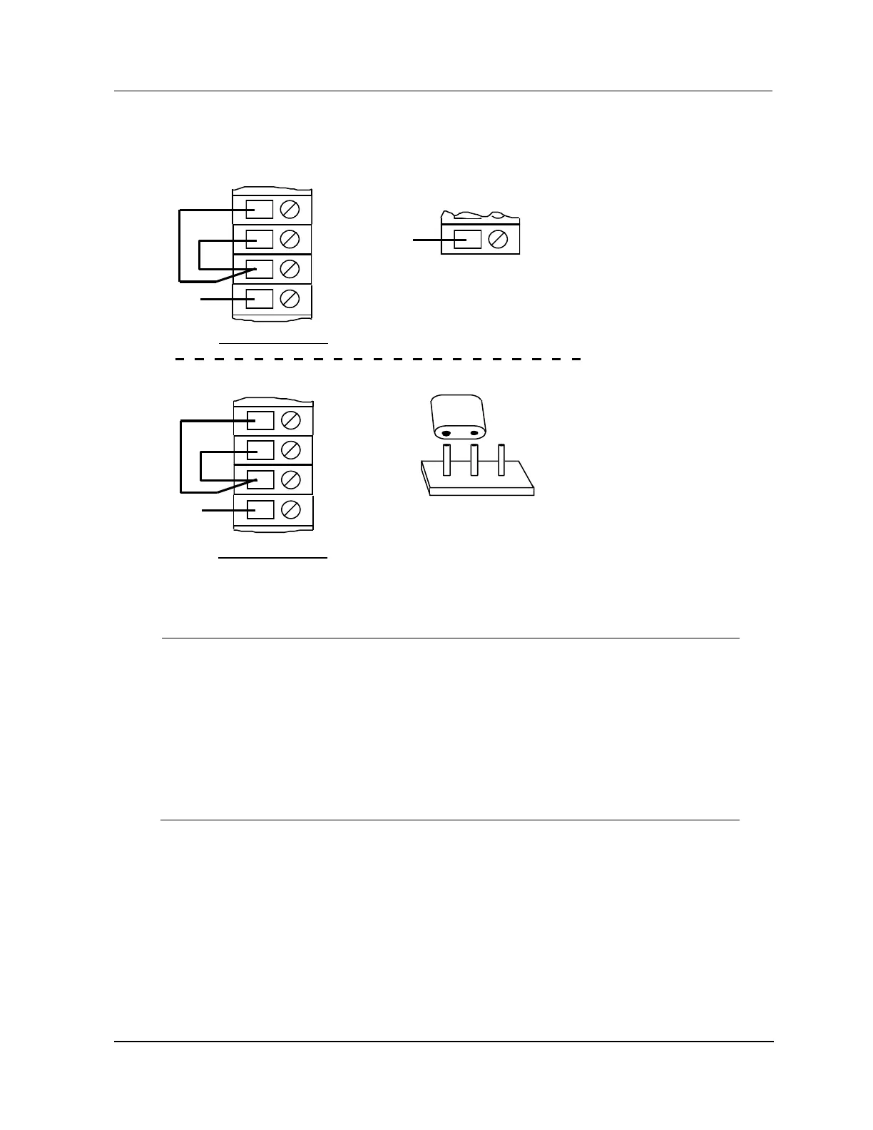
Figure 209 Zero Calibration Circuit – RTD ZeroCu: 10 Ohm, Pt: 100 Ohm, Ni: 120 Ohm
A
B
C
Channels 1 through 8
NC
Shield
Model MU/MC-TAIL01 and MU/MC-TAIL02 FTAs
Model MU/MC-TAIL03 FTA
Channels 1 through 8
1 3
Install the jumper between pins 1 and 2
to disconnect the reference junction
sensor from channel 1.
2
P1
2484
NC
17
TB2
Remove the wire between TB-1 and
TB2-17 to disconnect the reference
junction sensor from channel 1.
Reference
A
B
C
NC
Shield
Select the ENABLE CALIBRATION (or ENABLE RJ CALIBRATION if an RJ
calibration is being performed) target on the Detail Status display for the LLAI. The
ENABLE CALIBRATION target changes to the DISABLE CALIBRATION target.
Momentarily short the two square calibrate pads in the upper-left corner of the
FTA under test, as shown in
Figure 210. Now check the STATUS indicator (DS1) on the associated LLAI FTA.
You will find it extinguishes immediately, then comes back on in approximately
30 seconds. During this time, the IOP card has performed its "zero input"
calibration.

 Loading...