INS
GUI User’s Manual
Inertial Labs, Inc
TM
Address: 39959 Catoctin Ridge Street, Paeonian Springs, VA 20129 U.S.A.
Tel: +1 (703) 880-4222, Fax: +1 (703) 935-8377 Website: www.inertiallabs.com
128
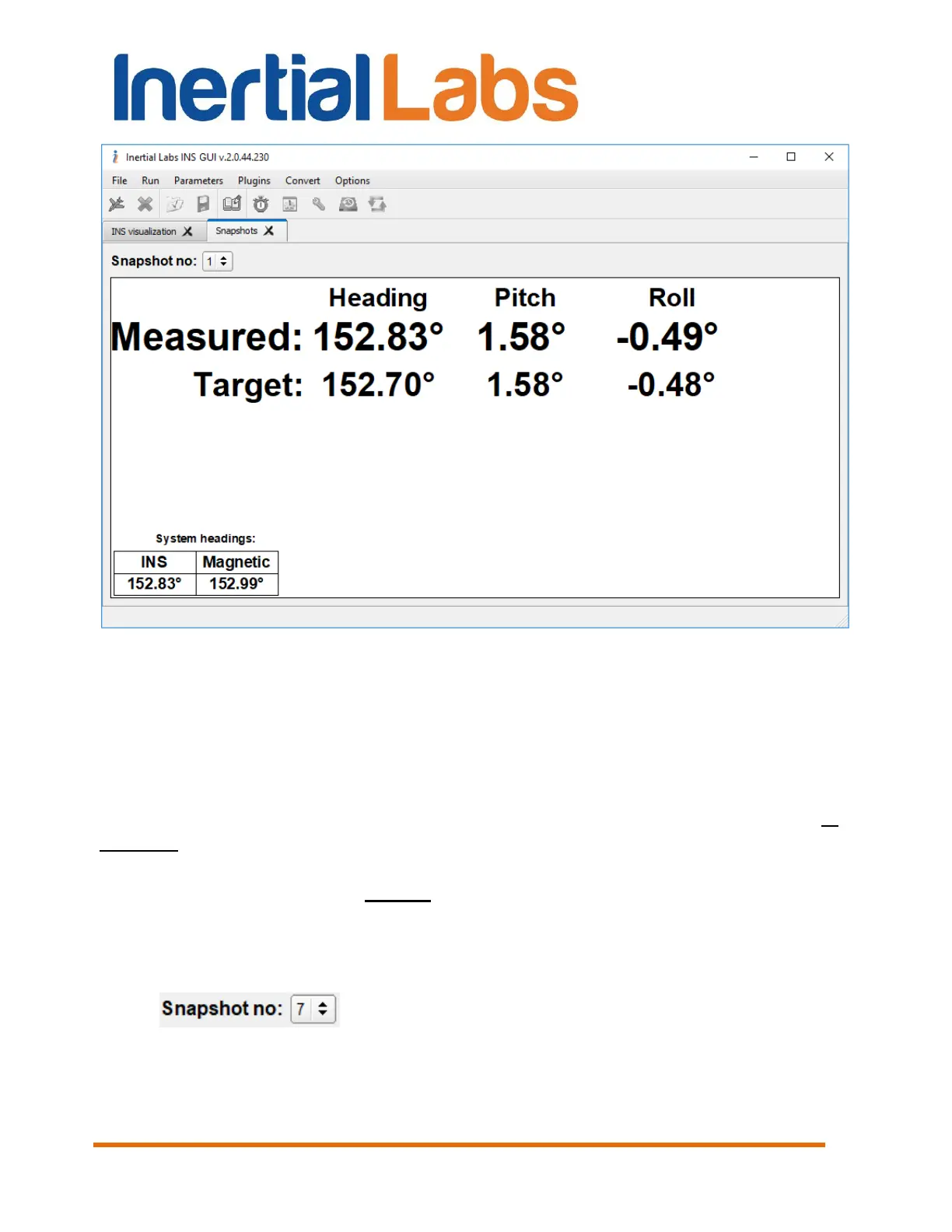
Fig. 10.21
Step 12. Rotate INS in the next position and repeat Step 11 as many
times as you need. Azimuth value for each new position can be entered in
the “Heading” field directly or as relative azimuth in the right field. It is
measured by means of object sight unit or separate device (like theodolite).
Azimuth of these relative position can be set in degrees or in mils depending
on chosen item in drop-down list “(deg) / (mils)”. Relative azimuth in
degrees is considered to be positive in case of clockwise rotation from
reference to calibration point and negative in case of counter-clockwise
rotation. Relative azimuth in mils is positive in case of counter-clockwise
rotation from reference to calibration point and negative in case of clockwise
rotation (according to sight unit scale).
You can verify all snapshots data by clicking on the arrow
button . After each snapshot calculation is performed and
graph Heading Error is plotted (Fig. 10.22). “Heading error (deg)” graph
shows difference between INS measurements and reference angles.

 Loading...