Memory Interface Routing
R
102 Intel
®
Pentium
®
4 Processor / Intel
®
850 Chipset Family Platform Design Guide
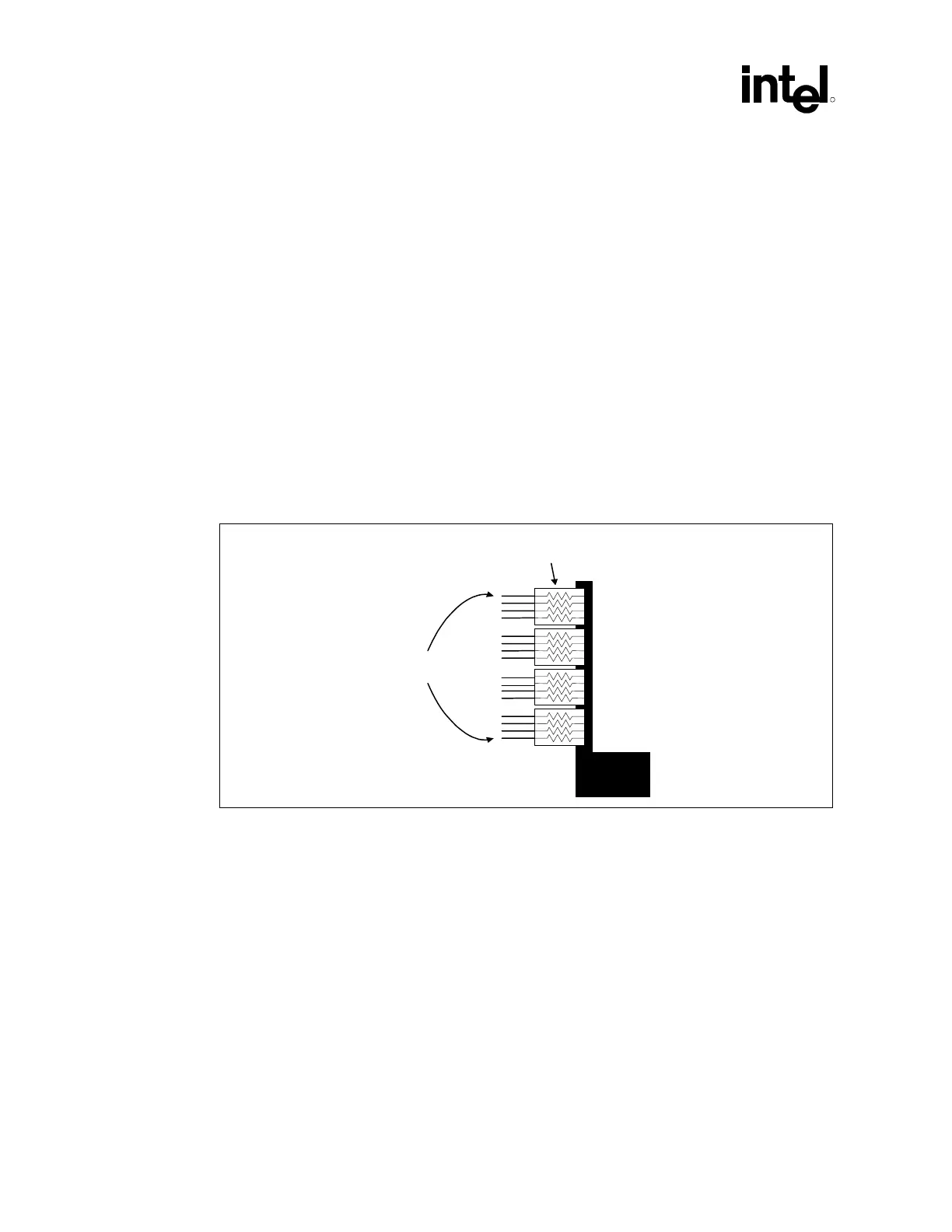
6.1.3 RSL Signal Termination
All RSL signals must be terminated to 1.8 V (Vterm) using 27 Ω 1% or 28 Ω 2% resistors
(300/400 MHz RDRAM technology) or 27 Ω 1% (533 MHz RDRAM technology) at the end of
the channel opposite the MCH. Resistor packs are acceptable, however discrete resistors are
recommended for increased margin. The RSL and clocking signals from the last RIMM connector
to termination should be routed on the top layer. Vterm must be decoupled using high-speed
bypass capacitors (one 0.1 µF ceramic chip capacitor per two RSL lines) near the terminating
resistors. For margin improvement, the number of bypass capacitors can be increased to two 0.1µF
ceramic chip capacitors per two RSL lines. Additionally, bulk capacitance is required. Assuming a
linear regulator with approximate 20 µs response time, two 100 µF tantalum capacitors are
recommended. The trace length between the last RIMM connector and the termination resistors
should be less than 2 inches. Length matching in this section of the channel is not required. The
Vterm power island should be AT LEAST 50 mils wide. This voltage is not required during
Suspend-to-RAM (STR).
Figure 65. Direct Rambus RDRAM* Device Termination (Discrete Resistors Are
Recommended)
Vterm
RSL
Signals
Termination
Resistors