Memory Interface Routing
R
96 Intel
®
Pentium
®
4 Processor / Intel
®
850 Chipset Family Platform Design Guide
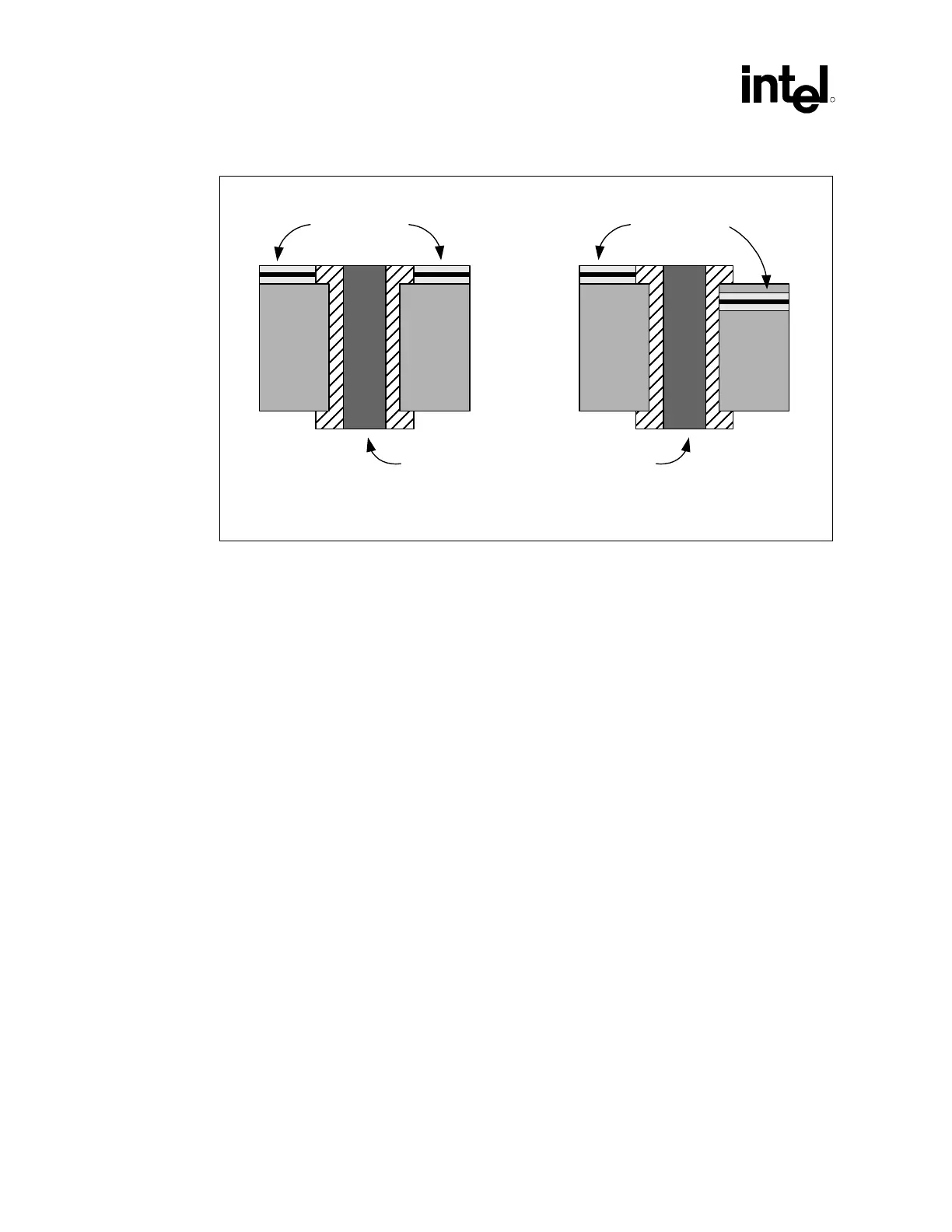
Figure 60. "Dummy" vs. "Real" Vias
“DUMMY Via”
PCB PCB
“REAL Via”
PCB PCB
Trace
Trace
Via Via
dum_vias_vs_real
6.1.2.3 Differential Clock Compensation
If the RDRAM device clocks (CTM, CTM#, CFM and CFM#) are routed differential, the clock
signals must be longer than the RSL signals due to their increased trace velocity because they are
routed as a differential pair. To calculate the length for each clock, use Equation 4 for microstrip
and Equation 5 for stripline routing.
Equation 4. Clock Trace Length Calculation for Microstrip
300/400 MHz RDRAM technology:
CFM/CFM# Clock Length = Nominal RSL Signal Length (package + board)* 1.030
(1)
CTM/CTM# Clock Length = Nominal RSL Signal Length (package + board)* 1.030
(1)
533 MHz RDRAM technology:
CFM/CFM# Clock Length = Nominal RSL Signal Length (package + board)* 1.030
(1)
CTM/CTM# Clock Length = Nominal RSL Signal Length (package + board)* 1.030 + 45
pS
(1)