Schematic Review Checklist
R
Intel
®
Pentium
®
4 Processor / Intel
®
850 Chipset Family Platform Design Guide 243
15 Schematic Review Checklist
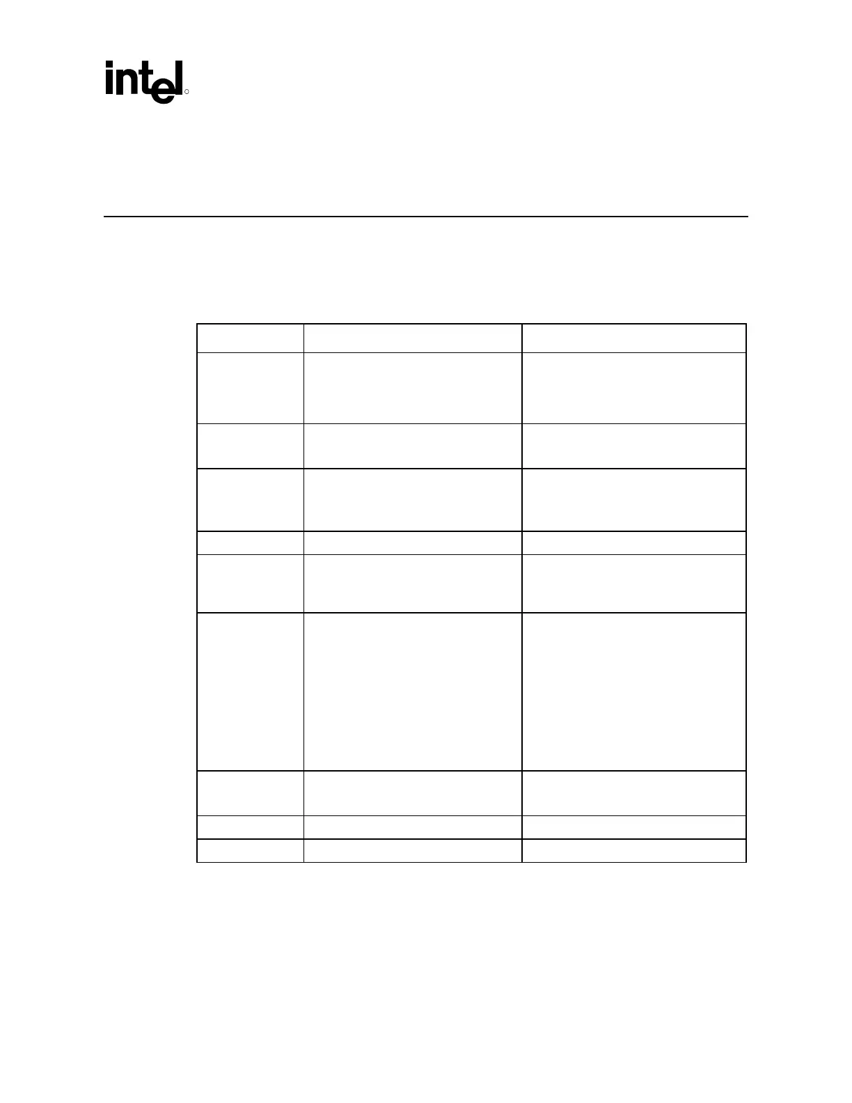
15.1 Processor Checklist (All Signals)
All signals of the processor are provided in this section.
Checklist Items Recommendations Reason/Impact/Documentation
A[35:3]#
• Connect A[31:3]# to MCH. Leave
A[35:32]# as No Connect.
• Chipset does not support extended
addressing over 4 GB, leave A[35:32]#
unconnected.
• AGTL+ source synch I/O signal
A20M# • Connect to ICH2. No pull-up required. • Asynch GTL+ Input Signal
• Refer to Section 5.4.1.2.
ADS# • Connect to MCH • AGTL+ common clock I/O signal
ADSTB[1:0] • Connect to MCH • AGTL+ source synch I/O signal
AP[1:0]# • Leave as No Connect • Chipset does not support parity
protection on the address bus.
• AGTL+ common clock I/O signal
BCLK[1:0] • Connect to CK00 clock. Refer to clock
routing guidelines in the latest
revision of the design guide.
• Connect 33 Ω series resistor on each
clock signal.
• Connect a “shunt source termination
(Rt)” resistor to GND for each signal
on processor side of the series
resistor. The Rt value should be
49.9
Ω ±1% for 50 Ω MB impedance.
• Rt resistors should be selected to
match the characteristic impedance of
the board.
• System bus clock signal
• Refer to Section 4.1of this document.
BINIT# • Leave as No Connect. • Chipset does not support this signal.
• AGTL+ common clock I/O signal
BNR# • Connect to MCH • AGTL+ common clock I/O signal
BPRI#
• Connect to MCH • AGTL+ common clock input signal