AGP Interface Routing
R
Intel
®
Pentium
®
4 Processor / Intel
®
850 Chipset Family Platform Design Guide 115
20 mils (1:4). The strobe pair must be length matched to less than ±0.1 inches (i.e., a strobe and its
compliment must be the same length within 0.1 inches).
If the board impedance is 15%, the trace spacing increases to 20 mils. See the AGP interfaces
trace length summary section for detailed information regarding 15% tolerance signals.
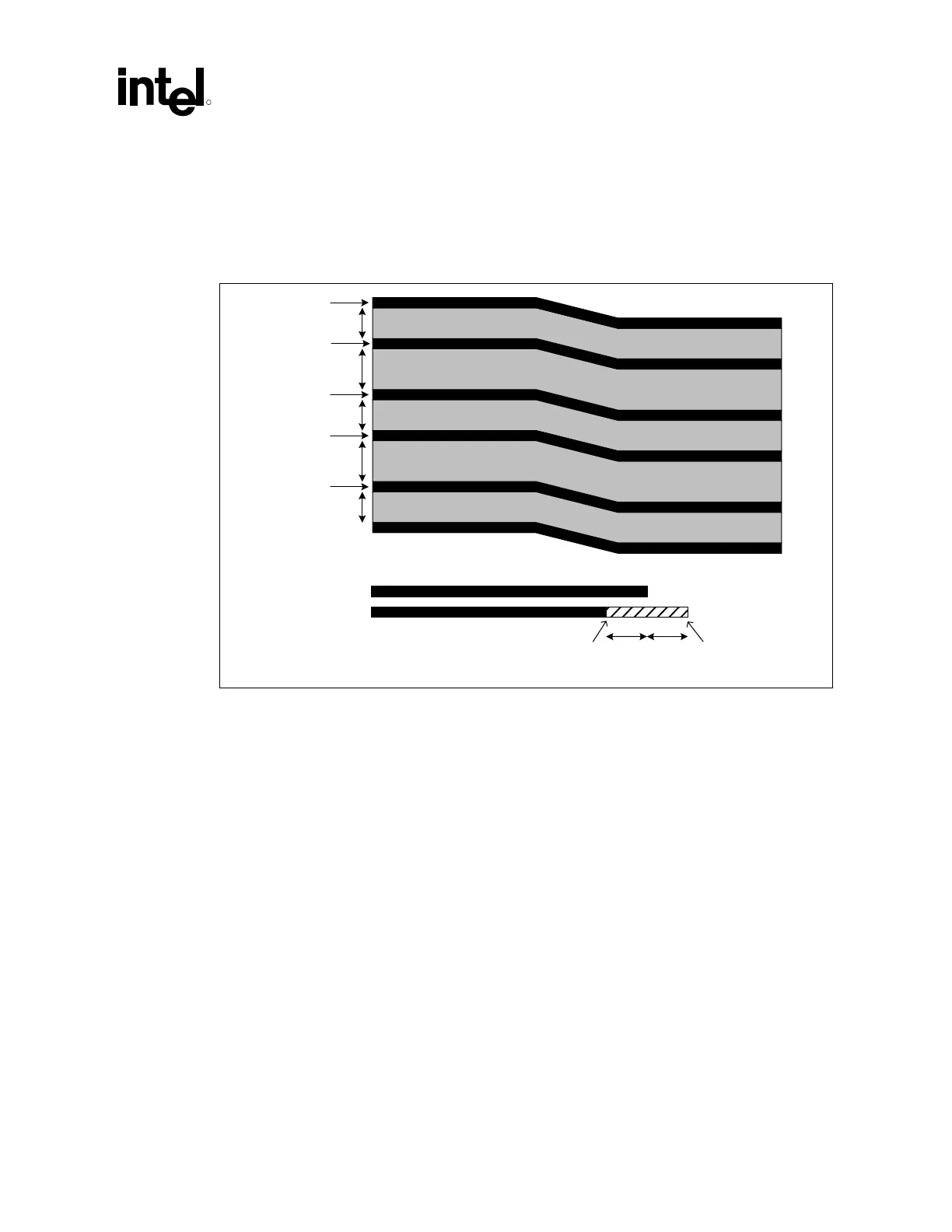
Figure 75. AGP 2X/4X Routing Example for Interfaces < 6 Inches
2X/4X Signal
2X/4X Signal
AGP STB#
AGP STB
2X/4X Signal
2X/4X Signal
15 mils
15 mils
15 mils
20 mils
20 mils
5 mil trace
5 mil trace
5 mil trace
5 mil trace
5 mil trace
2X/4X Signal
2X/4X Signal
AGP STB#
AGP STB
2X/4X Signal
2X/4X Signal
STB/STB# Length
Associated AGP 2X/4X Data Signal Length
Min Max
0.5" 0.5"
AGP_2X-4X_Routing
7.1.2.2 Trace Lengths Greater Than 6 Inches and Less Than 7.25 Inches
Longer lines have more crosstalk. Therefore in order to reduce skew, longer line lengths require a
greater amount of spacing between traces. For line lengths greater than 6 inches and less than
7.25 inches, 1:4 routing is required for all data lines and strobes with a 10% tolerance impedance.
For these designs, the line length mismatch must be less than ±0.125 inches within each signal
group (between all data signals and the strobe signals).
For example, if a set of strobe signals (e.g., AD_STB0 and AD_STB0#) are 6.5 inches long, the
data signals that are associated to those strobe signals (e.g., AD[15:0] and C/BE[2:0]#), can be
6.475 inches to 6.625 inches long. Another strobe set (e.g., SB_STB and SB_STB#) could be
6.2 inches long, and the data signals that are associated to those strobe signals (e.g. SBA[7:0]), can
be 6.075 inches to 6.325 inches long.
The strobe signals (AD_STB0, AD_STB0#, AD_STB1, AD_STB1#, SB_STB, and SB_STB#)
act as clocks on the source synchronous AGP interface; therefore special care must be taken when
routing these signals. Because each strobe pair is truly a differential pair, the pair should be routed
together (e.g., AD_STB0 and AD_STB0# should be routed next to each other). The two strobes in
a strobe pair should be routed on 5 mil traces with at least 20 mils of space (1:4) between them.
This pair should be separated from the rest of the AGP signals (and all other signals) by at least
20 mils (1:4). The strobe pair must be length matched to less than ±0.1 inches (that is, a strobe and
its compliment must be the same length within 0.1 inches).