Layout Review Checklist
R
284 Intel
®
Pentium
®
4 Processor / Intel
®
850 Chipset Family Platform Design Guide
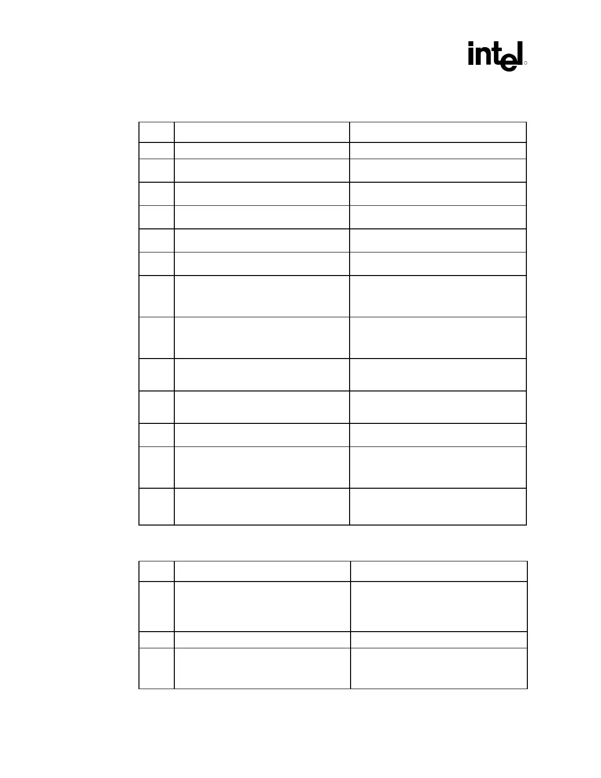
16.4.2.2 AGP Interface Greater Than 6 Inches and Less Than 7.25 Inches
√ Recommendations Reason/Impact
• Board impedance must be 60 Ω ±10% • Refer to Section 7.1.2.2.
• 5 mil trace width 20 mil separation between
data to data
• Refer to Section 7.1.2.2.
• 5 mil trace width 20 mil separation between
data (and all other signals) to strobes
• Refer to Section 7.1.2.2.
• 5 mil trace width 20 mil separation between
strobe to strobe
• Refer to Section 7.1.2.2.
• DATA and C/BE#s need to be length
matched within ±0.125 inches of strobes.
• Refer to Section 7.1.2.2.
• Strobe pairs must be length matched ±0.1
inches
• Refer to Section 7.1.2.1.
• Route AD[15:0], C/BE[1:0]#, AD_STB0, and
AD_STB0# together. (Good
recommendation, but not in the AGP
specification)
• Signals to be kept on same layers.
Microstrip-to-microstrip and stripline-to-
stripline.
• Route AD [31:16], C/BE [3:2]#, AD_STB1,
and AD_STB1# together. (Good
recommendation, but not in the AGP
specification)
• Signals to be kept on same layers.
Microstrip-to-microstrip and stripline-to-
stripline.
• Route SBA[7:0], SB_STB, SB_STB#
together. (Good recommendation, but not in
the AGP specification)
• Signals to be kept on same layers.
Microstrip-to-microstrip and stripline-to-
stripline.
• Recommended that all strobes be ground
referenced as well as TRDY#, IRDY#,
GNT#.
• Refer to Section 7.1.5.
• Recommended that ½ the AGP signals are
ground referenced.
• Refer to Section 7.1.5.
• For signals that require pull-up or pull-down
resistors, keep stub less than 0.5 inches for
1X signals and less than 0.01 inches for
2X/4X signals.
• This is to minimize signal reflections from
the stub.
• Refer to Section 7.1.9.
• Pour a VSS flood under V
DDQ
plane • Optimizes the mutual inductance between
two planes.
• Refer to Section 7.1.9.
16.4.3 Intel
®
MCH AGP Decoupling
√ Recommendations Reason/Impact
• Min of 6 0.01 µF capacitors spread evenly
around the MCH AGP interface.
• It is recommended that a low ESL ceramic
capacitor, such as a 0603 body type, X7R
dielectric.
• Refer to Section 7.1.4.
• Must be within 0.15 inches from package • Refer to Section 7.1.4.
• Pour a VSS flood under V
DDQ
plane to
decouple AGP.
• To help lower inductive path from the
decoupling capacitor.
• Refer to Section 7.1.4.