I/O Controller Hub 2
R
Intel
®
Pentium
®
4 Processor / Intel
®
850 Chipset Family Platform Design Guide 165
Table 38. Length Requirements for Single Solution Interconnect
Component Minimum (inches) Maximum (inches) Notes
82562EH L=4.5 L=10 Signal Lines LAN_RXD[2:1] and
LAN_TXD[2:1] not connected
82562ET L=3.5 L=10
CNR L=3 L=9
NOTE: Length of trace from connector to LOM should be 0.5 to 3 inches.
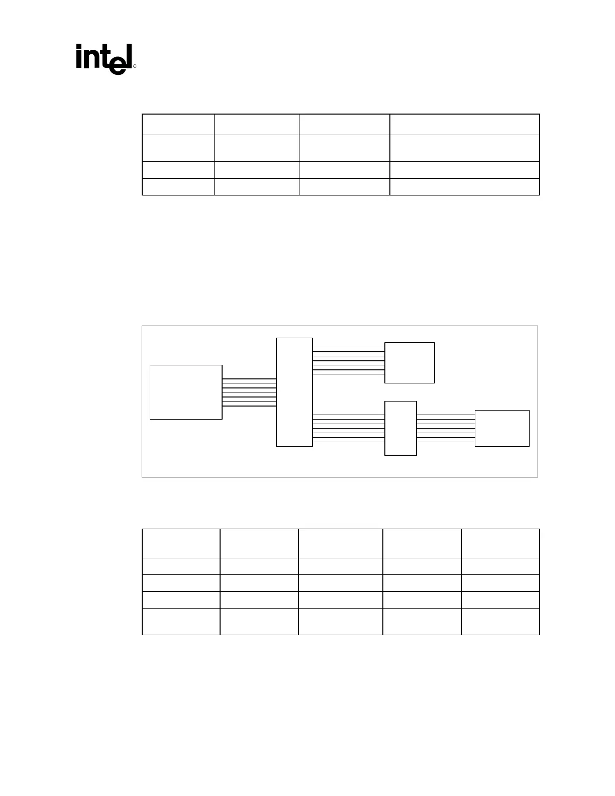
9.9.1.3 LOM/CNR Interconnect
The following guidelines allow for an all inclusive motherboard solution. This layout combines
LOM, dual footprint, and the CNR solutions. The resistor pack ensures that either a CNR option or
a LAN on motherboard option can be implemented at one time. The recommended trace routing
lengths are shown in Figure 119. LOM/CNR Interconnect.
Figure 119. LOM/CNR Interconnect
LAN_LOM-CNR_intercomm
ICH2
Res.
pack
CNR PLC card
B
A
PLC
C D
Table 39. Length Requirements for LOM/CNR Interconnect
Configuration Segment A
(inches)
Segment B
(inches)
Segment C
(inches)
Segment D
(inches)
82562EH 0.5 to 6.0 4 to 10 - A — —
82562ET 0.5 to 7 3 to 10 - A — —
Dual Footprint 0.5 to 6 4 to 10 – A — —
82562ET/EH
Card
1
0.5 to 6.5 — 2.5 to 9 – A 0.5 to 3
NOTES:
1
Total trace length should not exceed 13 inches.