Memory Interface Routing
R
92 Intel
®
Pentium
®
4 Processor / Intel
®
850 Chipset Family Platform Design Guide
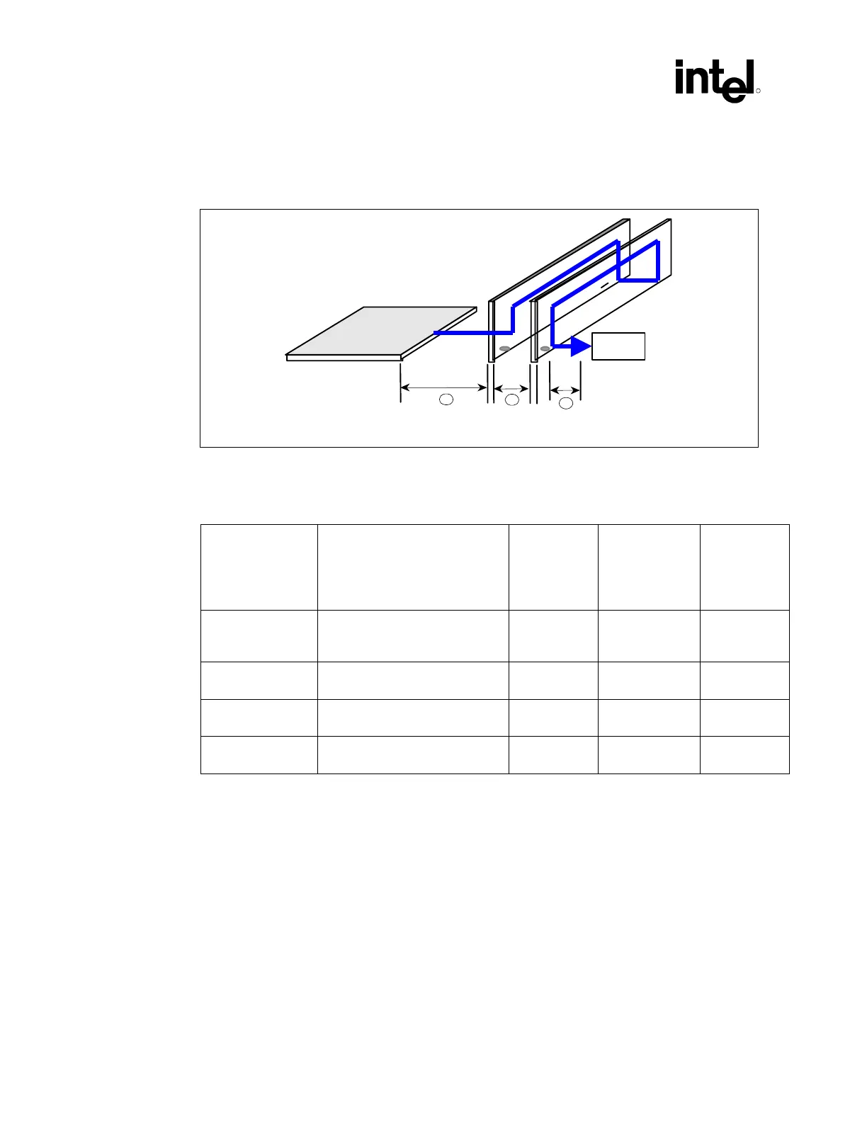
The following figure and table document the Direct Rambus channel topology for a 28 Ω channel.
Figure 57. Example Direct Rambus Channel Routing
MCH
MCH to
1
st
RIMM
RIMM to
RIMM
RIMM to
Termination
A
B
C
Term
NOTE: This diagram only illustrates the routing of one Direct Rambus channel. However, the example routing
shown can be applied to both channels.
Table 22. Direct Rambus RSL Signal Lengths for Rambus RIMM* Connectors on Motherboard
Reference
Section
Trace Description Trace
Length
300/400 MHz
RDRAM
Technolgty
Trace Length
533 MHz
RDRAM
Technology
(Microstrip)
Trace
Length
533 MHz
RDRAM
Technology
(Stripline)
A MCH to first RIMM* connector for
Channel A or first RIMM
connector for Channel B
1 to 6 inches 1 to 4 inches 1 to 4 inches
B RIMM connector to RIMM
connector for the same channel.
0.4 to 1
inches
0.4 to 1 inches 0.4 to 1
inches
C RIMM connector to Termination 0 to 2
inches
(1)
0 to 2 inches
(1)
0 to 2
inches
(1)
D A+B 7 inches max 4.4 inches max 4.4 inches
max
NOTES:
1. Place termination resistors between RIMM connectors of the same channel to decrease trace length if
possible.
2. For MCH to first RIMM connector measurement, use CFM/CFM# (CTM/CTM# use a different trace
length calculation based on the formulas specified in Section 6.1.2.3)