Intel® Pentium® 4 Processor in the 478-Pin Package Processor Power Distribution Guidelines
R
202 Intel
®
Pentium
®
4 Processor / Intel
®
850 Chipset Family Platform Design Guide
11.1.4 FMB2 Decoupling Requirements
In order for the processor voltage regulator circuitry to meet the transient specifications of the
processor, proper bulk and high frequency decoupling is required. The decoupling requirements
for the processor power delivery in this case are described in Table 48 and Table 49.
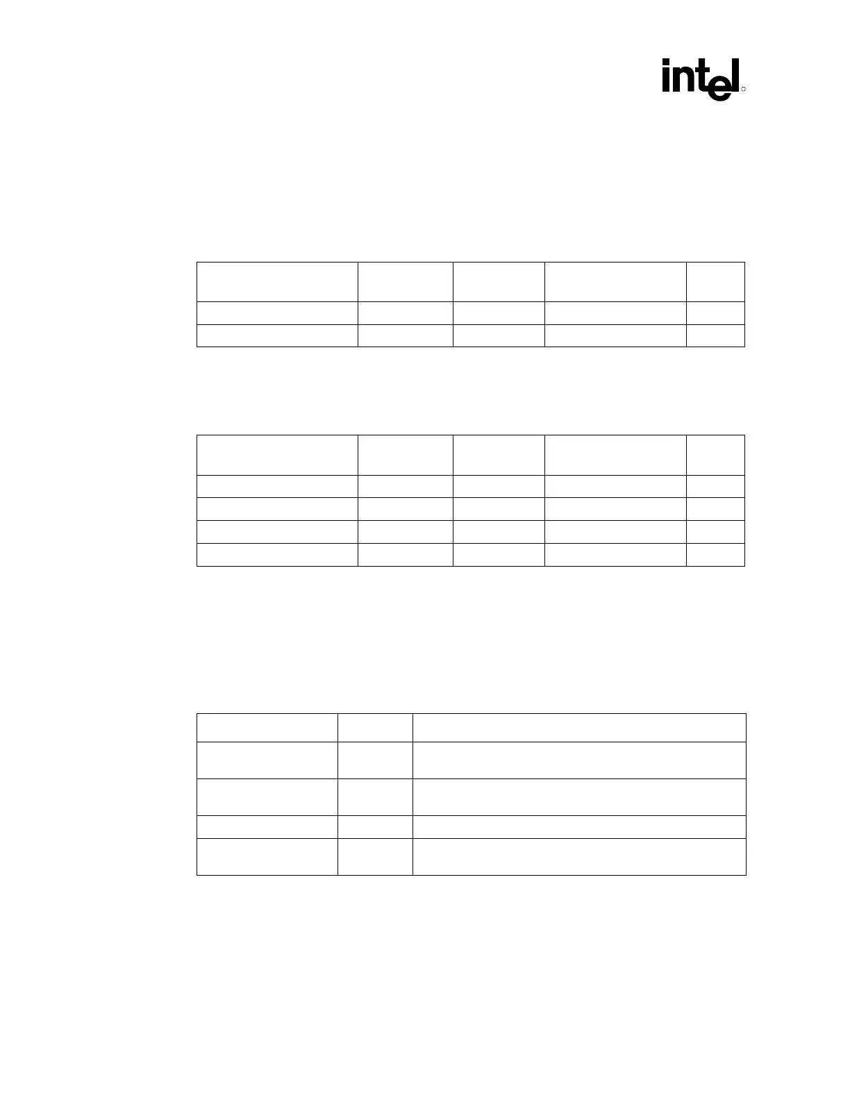
Table 48. Four-Phase Decoupling Requirements
Capacitance ESR
(Each)
ESL
(Each)
Ripple Current Rating
(Each)
Notes:
10 OSCONs*, 560 µF 9.28 mΩ, max 6.4 nH, max 4.080 A 1
38 1206 package, 10 µF 3.5 mΩ, typ 1.15 nH, typ 1
NOTES:
1. The ESR, ESL and ripple current values in this table are based on the values used in power delivery
simulation by Intel and they are not vendor specifications.
Table 49. Three-Phase Decoupling Requirements
Capacitance ESR
(Each)
ESL
(Each)
Ripple Current Rating
(Each)
Notes:
9 OSCONs*, 560 µF 9.28 mΩ, max 6.4 nH, max 4.080 A 1
3 AI Electrolytic, 3300 µF 12 mΩ 5 nH 1
24 0805 package, 10 µF 1,2
14 1206 package, 10 µF 3.5 mΩ, typ 1.15 nH, typ 1,2
NOTES:
1. The ESR, ESL and ripple current values in this table are based on the values used in power delivery
simulation by Intel and they are not vendor specifications.
2. If only 1206’s are used, 38 are needed.
The decoupling should be placed as close as possible to the processor power pins. Table 50 and
Table 51 and Figure 144 and Figure 145 describe and illustrate the recommended placement.
Table 50. Four-Phase Decoupling Locations
Type Number Location
560 µF OSCONs* 10 North side of the processor as close as possible to the keep-out
area for the retention mechanism
1206 package, 10 µF 13 North side of the processor as close as possible to the
processor socket
1206 package, 10 µF 12 Inside the processor socket cavity
1206 package, 10 µF 13 South side of the processor as close as possible to the
processor socket