I/O Controller Hub 2
R
Intel
®
Pentium
®
4 Processor / Intel
®
850 Chipset Family Platform Design Guide 135
9.1.2.1 Combination Host-Side/Device-Side Cable Detection
Host side detection (described in the ATA/ATAPI-4 Standard, Section 5.2.11) requires the use of
two GPI pins (one for each IDE channel). The proper way to connect the PDIAG#/CBLID# signal
of the IDE connector to the host is shown in Figure 87. All IDE devices have a 10 kΩ pull-up
resistor to 5 volts on this signal. Not all of the GPI and GPIO pins on the ICH2 are 5-volt tolerant.
If non 5-volt tolerant inputs are used, a resistor divider is required to prevent 5 volts on the ICH2
or FWH pins. The proper value of the divider resistor is 10 kΩ (as shown in Figure 87).
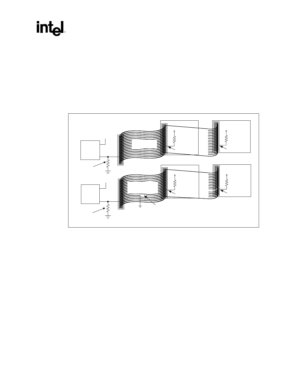
Figure 87. Combination Host-Side/Device-Side IDE Cable Detection
80-conductor
IDE cable
IDE drive
5 V
ICH2
GPIO
GPIO
Open
IDE drive
5 V
40-conductor
cable
IDE drive
5 V
PDIAG#
ICH2
GPIO
GPIO
IDE drive
5 V
PDIAG#
PDIAG#PDIAG#
10 kΩ
10 kΩ
To secondary
IDE connector
PDIAG#/
CBLID#
PDIAG#/
CBLID#
10 kΩ
10 kΩ
10 kΩ
10 kΩ
IDE_combo_cable_det
Resistor required for
non 5V tolerant GPI
To secondary
IDE connector
Resistor required for
non 5V tolerant GPI
This mechanism allows the BIOS, after diagnostics, to sample PDIAG#/CBLID#. If the signal is
high then there is 40-conductor cable in the system and ATA modes 3, 4, and 5 must not be
enabled.
If PDIAG#/CBLID# is detected low, then there may be an 80-conductor cable in the system, or
there may be a 40-conductor cable and a legacy slave device (Device 1) that does not release the
PDIAG#/CBLID# signal as required by the ATA/ATAPI-4 standard. In this case, BIOS should
check the IDENTIFY DEVICE information in a connected device that supports Ultra DMA modes
higher than 2. If ID Word 93, bit 13 is a 1, then an 80-conductor cable is present. If this bit is 0,
then a legacy slave (Device 1) is preventing proper cable detection, and BIOS should configure the
system as though a 40-conductor cable is present, and notify the user of the problem.