I/O Controller Hub 2
R
166 Intel
®
Pentium
®
4 Processor / Intel
®
850 Chipset Family Platform Design Guide
Additional guidelines for this configuration are as follows:
• Stubs due to the resistor pack should not be present on the interface.
• The resistor pack value can be 0 Ω or 22 Ω.
• LAN on motherboard PLC can be a dual footprint configuration.
9.9.1.4 Signal Routing and Layout
LAN Connect signals must be carefully routed on the motherboard to meet the timing and signal
quality requirements of this interface specification. The following are some general guidelines that
should be followed. It is recommended that the board designer simulate the board routing to verify
that the specifications are met for flight times and skews due to trace mismatch and crosstalk. On
the motherboard the length of each data trace is either equal in length to the LAN_CLK trace or up
to 0.5 inches shorter than the LAN_CLK trace. (LAN_CLK should always be the longest
motherboard trace in each group.)
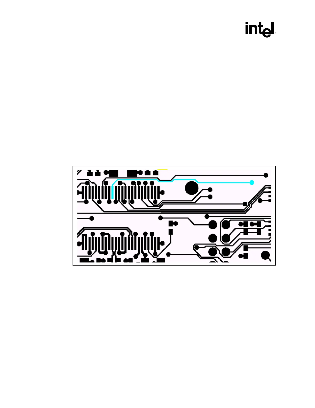
Figure 120. LAN_CLK Routing Example
9.9.1.5 Crosstalk Considerations
Noise due to crosstalk must be minimized. Crosstalk is the key cause of timing skews and is the
largest part of the t
RMATCH
skew parameter.
9.9.1.6 Impedances
The motherboard impedances should be controlled to minimize the impact of any mismatch
between the motherboard and the add-in card. An impedance of 60 Ω ±15% is strongly
recommended; otherwise, signal integrity requirements may be violated.