System Bus Routing
R
62 Intel
®
Pentium
®
4 Processor / Intel
®
850 Chipset Family Platform Design Guide
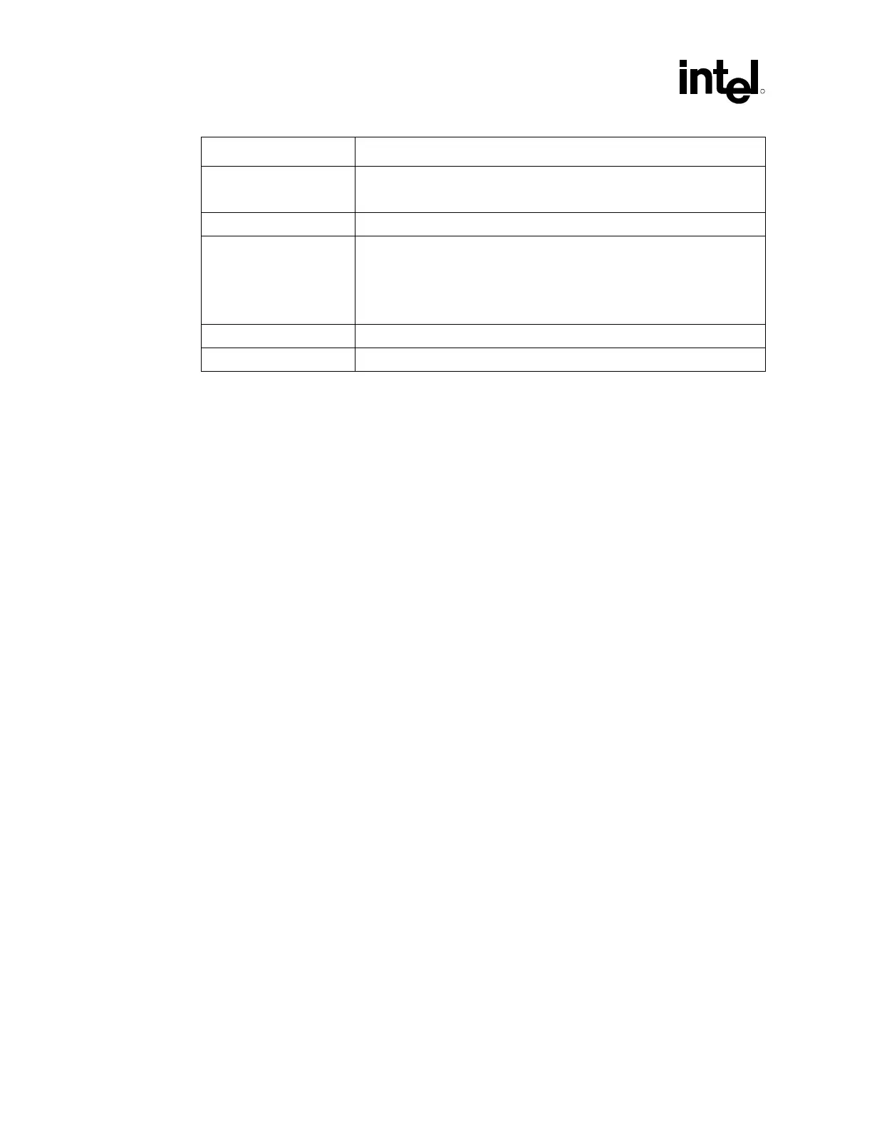
Parameter Processor Routing Guidelines
Common Clock line
lengths
6 – 10 inches pin to pin
No length compensation is necessary.
Topology Point to point (chipset to processor).
Routing priorities All signals should be referenced to VSS.
Ideally, layer changes should not occur for any signals. If a layer change
must occur, reference plane must be VSS and the layers must all be of the
same configuration (all stripline or all microstrip for example). Refer to
Section 5.3 for specific details.
Clock Keepout Zones Clocks pairs should have 20 mils spacing from other signals.
Trace Impedance 50 ohms ± 15% for 7 mil traces
5.1 Return Path
The return path is the route current takes to return to its source. It may take a path through ground
planes, power planes, other signals, integrated circuits, vias, VRMs etc. It is useful to think of the
return path as following a path of least resistance back to the original source. Discontinuities in the
return path often have signal integrity and timing effects that are similar to the discontinuities in
the signal conductor. Therefore, the return paths need to be given similar considerations. A simple
way to evaluate return path parasitic inductance is to draw a loop that traces the current from the
driver through the signal conductor to the receiver, and then back through the ground/power plane
to the driver again. The smaller the area of the loop, the lower the parasitic inductance will be.
The following sets of return path rules apply:
• Always trace out the return current path and provide as much care to the return path as the
path of the signal conductor.
• Decoupling capacitors do not adequately compensate for a plane split.
• Do not allow splits in the reference planes in the path of the return current.
• Do not allow routing of signals on the reference planes near system bus signals.
• Maintain VSS as a reference plane for all system bus signals.
• Do not route over via anti-pads or socket anti-pads.