Layout Review Checklist
R
274 Intel
®
Pentium
®
4 Processor / Intel
®
850 Chipset Family Platform Design Guide
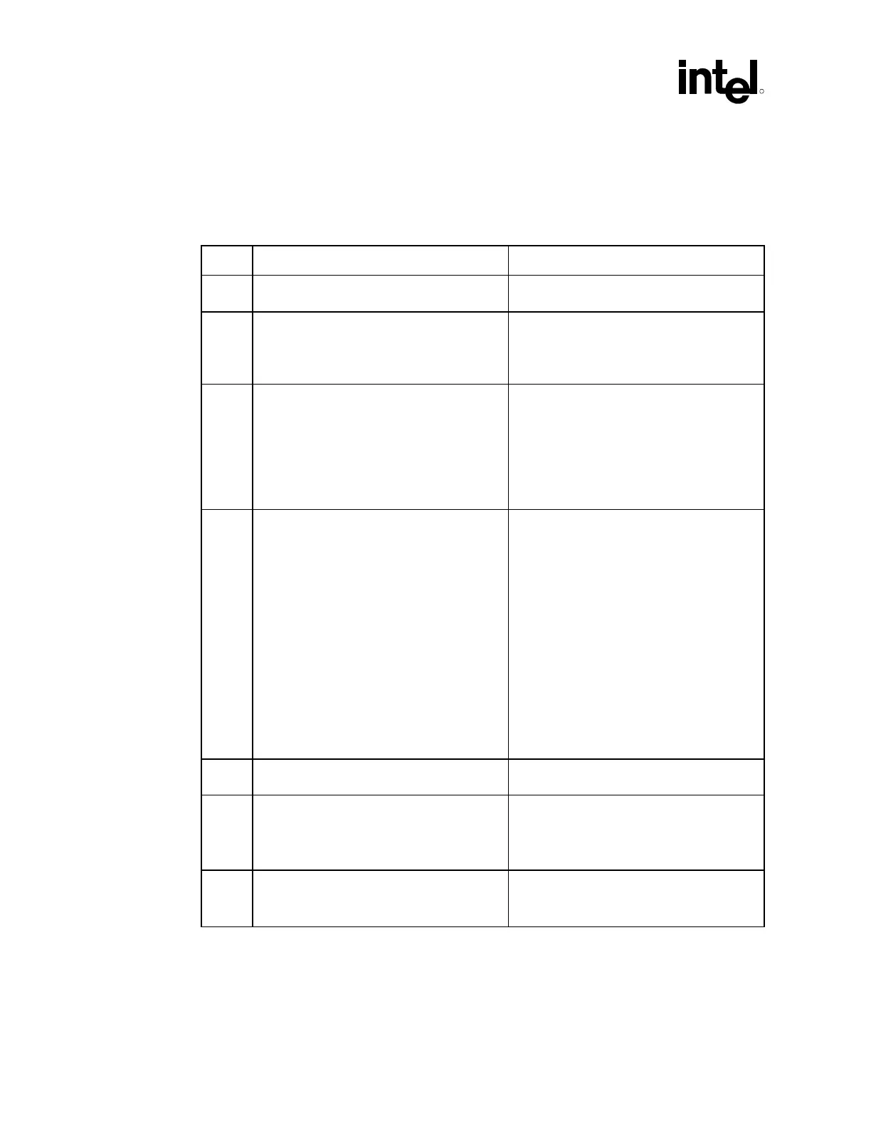
16.2 CK00 Routing Guidelines
16.2.1 CK00 Clocking
√ Recommendations Reason/Impact/Documentation
• 20 mil spacing required around all 100 MHz
differential clocks
• Refer to Section 4.1.
• Differential clocks should be routed on same
layer. If via is required, then dummy vias
need to be placed on other differential clock
signals.
• This recommendation is to minimize clock
skew due to clock pair to clock pair
inconsistencies.
• Refer to Section 4.1.
• Route 100 MHz differential clocks to all
agents on the same physical layer.
• Constraining all bus clocks to one physical
layer minimizes the impact on skew due to
variations in Er (dielectric constant) and
impedance due to physical tolerances of
circuit board material. Routing on internal
layers reduces impedance variations and
Er.
• Refer to Section 4.1.
• Connect individual differential clock signal
from the CK00 to the MCH, ITP port, and
the processor.
• CK00 to series resistor should be 0.5 inches
max.
• Series resistor to termination resistor node
should be 0.2 inches max. Termination
resistor node to actual termination resistor
should be 0.2 inches max. Termination
resistor node to processor socket should be
12 inches max for Host_CPU and Host_ITP
clocks.
• Termination resistor node to MCH should be
12 inches for Host_MCH clocks. Add 0.600
inches ± for length matching to Host_MCH
clock to compensate for processor socket
and package delay.
• Refer to Section 4.1
• Traces need to be 50 Ω ±15% single-ended
and 100
Ω differential.
• Refer to Section 4.1.
• Trace width for clocks is 7 mils and spacing
between each end of the differential clock
should be 7 mils. Uniform spacing should
be maintained through the entire length of
the trace.
• Degradation in noise rejection will occur if
spacing is not uniform.
• Refer to Section 4.1
• All host clocks must be ground referenced. • This ensures that proper current return path
is available.
• Refer to Section 4.1