I/O Controller Hub 2
R
Intel
®
Pentium
®
4 Processor / Intel
®
850 Chipset Family Platform Design Guide 189
9.16 PIRQ Routing
PCI interrupt request signals E-H are new to the ICH2. These signals have been added to lower the
latency caused by having multiple devices on one Interrupt line. With these new signals, each PCI
slot can have an individual PCI interrupt request line (Assuming that the system has four PCI
slots). Table 43 shows how the ICH2 uses the PCI IRQ when the IOAPIC is active.
Table 43. IOAPIC Interrupt Inputs 16 Through 23 Usage
IOAPIC INTIN PIN
Function in Intel
®
ICH2 using the PCI IRQ in IOAPIC
IOAPIC INTIN PIN 16 (PIRQA)
IOAPIC INTIN PIN 17 (PIRQB) AC’97, Modem and SMBUS
IOAPIC INTIN PIN 18 (PIRQC)
IOAPIC INTIN PIN 19 (PIRQD) USB Controller #1
IOAPIC INTIN PIN 20 (PIRQE) Internal LAN Device
IOAPIC INTIN PIN 21 (PIRQF)
IOAPIC INTIN PIN 22 (PIRQG)
IOAPIC INTIN PIN 23 (PIRQH) USB Controller #2 (starting from ICH2 B0 silicon)
Interrupts B, D, E, and H service devices internal to the ICH2. Interrupts A, C, F, and G are not
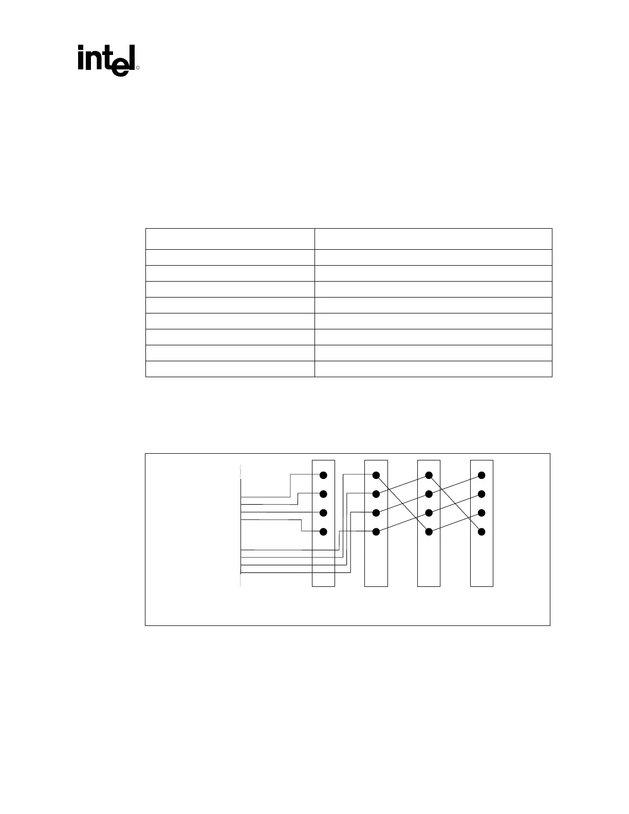
used and can be used by PCI slots. Figure 136 shows an example of IRQ line routing to the PCI
slots.
Figure 136. Example PCI IRQ Routing
ICH2
PIR
A#
PIRQB#
PIRQC#
PIRQD#
PIRQE#
PIRQF#
PIRQG#
PIRQH#
INTA
INTB
INTC
INTD
INTA
INTB
INTC
INTD
INTA
INTB
INTC
INTD
INTA
INTB
INTC
INTD
Slot 1
PCI Device 0
(AD16 to IDSEL)
Slot 3
PCI Device 6
(AD22 to IDSEL)
Slot 4
PCI Device C
(AD28 to IDSEL)
Slot 2
PCI Device 5
(AD21 to IDSEL)
The PCI IRQ Routing shown in Figure 136 allows the ICH2 internal functions to have a dedicated
IRQ(Assuming add-in cards are single function devices and use INTA). If a P2P bridge card or a
multifunction device uses more than one INTn# pin on the ICH2 PCI Bus, the ICH2 internal
functions will start sharing IRQs.
Figure 136 is an example. It is up to the board designer to route these signals in a way that is the
most efficient for their particular system. A PCI slot can be routed to share interrupts with any of
the ICH2’s internal device/functions.